0

I have Fibocom G510 modem. It has 2.85V logic level and datasheets says, that 3.3V is absolute maximum for logic pins. Maximum baud rate is 115200.

Due to the limited space in the housing / on PCB I do not have space for a proper level shifter.

Can I connect it to STM32F7 microcontroller with 3.3V logic level using resistors in series, like this?

enter image description here

I have tried this already, but I'm worried about long term consequences and 3.3V voltage that sometimes can be 3.4V due to power supply components tolerance.

Maybe I should use higher value resistors, like 1k to make it safer?

Kamil
  • 6,004
  • 9
  • 43
  • 60
  • This question has been asked many times in various forms. Have you searched from already-answered questions? You should find many answers. – TonyM Jun 29 '22 at 12:24
  • I couldn't find anything about this particular modem. I only found information about SIM8xx modems, that have max pin voltage at 3.0V and level shifter there is necessary. – Kamil Jun 29 '22 at 12:28
  • The modem's irrelevant, though, it's just a logic I/O device. Your question's just about interfacing 3.3 V logic to logic gates at different voltages. – TonyM Jun 29 '22 at 12:37
  • The problem is that only chinese manufacturer knows how these gates are made. There is no information about input impedance, ESD protection at all. – Kamil Jun 29 '22 at 13:05
  • 1
    I'm afraid I can only repeat the same point: search for questions about interfacing 3.3 V logic to logic gates at different voltages. The modem and its gates are irrelevant to the answer. You can avoid people having to write those same answers again. – TonyM Jun 29 '22 at 13:08
  • You could use a diode-resistor circuit to drop approximately 0.7V. Is 2.6V a valid logic high signal? – user253751 Jun 29 '22 at 16:43
  • @Kamil Does the 2.85V model draw any current? – Miss Mulan Jun 29 '22 at 18:07
  • @user253751 we dont know if there is current going into the 2.85V model , else I agree with your proposal. – Miss Mulan Jun 29 '22 at 18:17
  • @MissMulan hence the resistor – user253751 Jun 29 '22 at 18:21
  • @user253751 if current doesnt go in the 2.85V modem then no matter what you put in between wont affect the input voltage of the 2.85V modem. – Miss Mulan Jun 29 '22 at 18:26
  • @MissMulan ... hence the resistor to draw some current through the diode – user253751 Jun 30 '22 at 10:08
  • @user253751 you are preassuming that current flows inside the 2.85V modem but that may not be true. – Miss Mulan Jun 30 '22 at 10:10
  • @MissMulan no, I am not. – user253751 Jun 30 '22 at 10:11
  • @user253751 if current doesnt flow inside the 2.85V modem then no matter what you put between the 3.3V logic microcontroller and the 2.85V modem then the voltage drop will be 0 ->the modem will have a input voltage of 3.3V – Miss Mulan Jun 30 '22 at 10:13
  • @MissMulan counterexample: resistor connected between the modem pin and the microcontroller's ground pin. – user253751 Jun 30 '22 at 10:13
  • @user253751 you have used a 3rd pin then which you dont mention at all. – Miss Mulan Jun 30 '22 at 10:15
  • 1
    @MissMulan I never said anything about using no more than 2 pins. It seems like you are picking a fight for no good reason. – user253751 Jun 30 '22 at 10:15
  • @user253751 in the case of a 3rd pin I agree. – Miss Mulan Jun 30 '22 at 10:18

1 Answers1

1

Typically, an input pin on a non-trivial chip has diode clamps. The randomly selected picture below shows a typical setup.

Adapted from Figure 71. Basic structure of an I/O port bit - ST Microelectronics STM32 RM0468

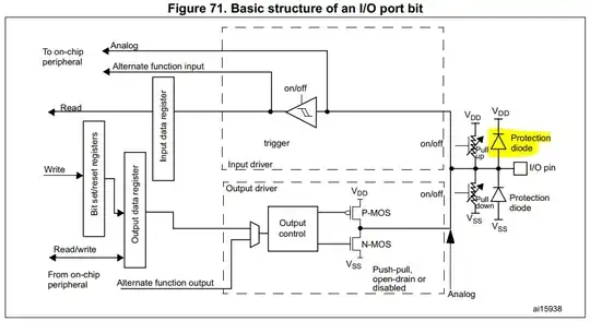
Adapted from image source: ST Microelectronics - STM32 reference manual RM0468

I highlighted the protection diode. If you apply an excessive voltage to the I/O pin, this diode is going to try to conduct current to its own power supply (Vdd). Uncontrolled amperage can blow parts up here if not controlled.

Therefore, on your signal from the 3.3V-supplied TX to the 2.85V-supplied RX, you want a resistor that is going to keep the amperage under control. Assuming some worst-case conditions and rounding numbers, a 1k resistor would keep things under a milliamp, so my casual suggestion would be that a 1k resistor should be your minimum on your "upper" resistor, and you could use larger if you like. This is a common practice.

For your "lower" resistor, I would not recommend a resistor in-line for the purpose of interfacing (although an inline resistor could appear there for other unrelated reasons, like smoothing edges that ruin your EMC emissions).

The concern I have there is if a worst-case voltage coming out of the modem is high enough to be recognized as a valid input by the microcontroller. For example, if that pin puts out 2.4 V as a minimum valid high output and your microcontroller accepts a minimum high input at 2.5 V, then you have a problem. Therefore, a pull-up resistor to 3.3 V would not be a bad idea. You could try to see if it works reliably without the pull-up populated, but if this was a PCB design I'd put one in just in case.

Note that this answer depends on some very typical assumptions about the devices you are using. Your results may vary.

SamGibson
  • 17,870
  • 5
  • 40
  • 59
Smith
  • 1,158
  • 5
  • 11
  • Thank you for breaking down the problem and the information that the 1k resistor is typical practice. This is what I needed. I calculated maximum current for 100Ohm and 3.3-2.85V and it was almost 5mA. Modem survived this, and looks like clamping diode works. With 1k current will be under 1mA, so probably any built-in clamping diode should survive this. Regarding the other way - it works fine in 99.999% cases. Sometimes (near 0.001% cases) STM32 loose one character at the beginning of transmission, but I'm not sure if this is the reason, or I have something messed up in ISR. – Kamil Jun 29 '22 at 23:06
  • Just for clarification - by "my upper resistor" you mean the resistor between 3.3V TX and 2.85V RX, right? – Kamil Jun 29 '22 at 23:06
  • Yes, the top one in your schematic. – Smith Jun 30 '22 at 15:15
  • To be honest, if I was doing your design above, I'd make the top resistor 10k, remove the bottom resistor, and put in a 10k pull-up on that lower signal and see how it goes. – Smith Jun 30 '22 at 15:22