0

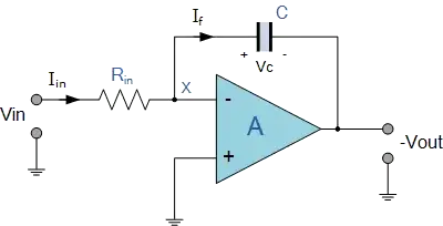
enter image description here

Someone told me that this circuit does not work unless there is DC bias path in the feedback. Because the op-amp is operating open loop for DC. Someone also told me that the input transistor pair of the op-amp need a bias voltage and thats another reason why there needs to be a feedback path.

Can someone explain this to me?

4 Answers4

1

All op-amps have some bias current at the inputs. It may be in or out depending on the technology and design and is normally listed on the datasheets.

If you consider the case when VIN is grounded the bias current will go to ground through RIN and this will cause the voltage at X to rise (assuming the bias current is exiting the non-inverting input). The small voltage difference between the inputs will be multiplied by the open-loop gain (and by -1 since V- > V+) and will start to drive negative. If left unchecked the output will eventually hit the negative rail.

Means of dealing with this are,

  • Using op-amps with very low bias.

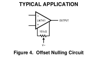
enter image description here

Figure 1. From What is "offset null" in IC 741?

  • Making offset adjustments. Famously the 741 had offset-null input which was connected to a trim-pot if required.
  • Use commutating auto-zero techniques.
  • Add a high value resistor in parallel with C. This reduces the ability to integrate low frequency and DC accurately.
  • Routine reset by shorting out C from time to time.
Transistor
  • 175,532
  • 13
  • 190
  • 404
  • Hmm. So what is the actual reason for saturation? Is it because the capacitor is integrating the DC component OR is it because the op-amp amplifies this small DC voltage at its input by the open loop gain? Which is it? – alayoiskgfbfqhxjiw May 21 '22 at 13:52
  • The output is going negative to pull a little current into the left hand side of C so that V- is the same as V+. Effectively it's pulling the bias current into C so that none is flowing through R. – Transistor May 21 '22 at 16:17
1

‘Does not work’ is rather a broad statement. If there’s even the smallest DC offset at the input then the output will eventually go all the way to one rail or the other, that’s the nature of integration. Depending on the application you might want some kind of DC feedback, but then the circuit wouldn’t be a ‘true’ integrator.

Frog
  • 7,287
  • 1
  • 9
  • 13
1

Integrators are used frequently. In systems with negative feedback, drift can be corrected due to either or both input bias current or capacitor leakage. Choosing low leakage caps made of certain plastics improves this greatly. "Chopper Op Amps use the signal switched to rapid normal/inverted polarities to eliminate the DC problem in some for very low drift.

Simple Theory

enter image description here

Integration supports eliminating static errors to zero in servo control systems.

Analog switches may be used to shunt integrator caps to perform Integrate & Dump over a data signal to determine the polarity of every period much more accurately than just sampling a noisy data signal.

The Op-Amp (OA) drives the output in the oppositive direction with negative feedback to match the Vin+= Vin-

This null difference is also called a Virtual ground since when the OA is operating in the linear range the input is consider "null" due to the error correct by the gain of the feedback. Electrical "Ground" is defined as 0V at one point.

  • We assume that care is taken to minimize significant voltage drop in conductors that share that "ground" so it remains at 0V due to resistance or inductance. Also the integration time must be much greater than the capacitor RC leakage time constant to minimize errors.

The Vin controls the R current which equals the Capacitor current as the OA drives the cap to match the input current by nulling the differential voltage with gain.

The capacitor voltage integrates its current within the voltage range of its specifications.

There are many more applications. Here's a simple integrator with some leakage resistance added. You can change any value with a mouse wheel.

Tony Stewart EE75
  • 1
  • 3
  • 54
  • 185
0

At first, the following question must be answered: Where (in which system) is such an integrating stage intended to be used?

It is correct, that the shown inverting Integrator will not work as desired (as an integrating device) when it is used as a "stand-alone block" - perhaps in series with other devices.

This is because any (unwanted) DC offset voltage at the opamp output (can never be avoided) will continuously charge the capacitor up to the maximum limit (supply voltage, saturation). In this case, a feedback resistor Rf in parallel to the feedback capacitor limits the DC gain to -Rf/Rin and, thus, can avoid saturation.

Of course, this resistor Rf will degrade the integrating capabilities of the circuit (smaller frequency range) - hence, a trade-off must be found between (a) the maximum allowable DC-offset at the opamp output and (b) the integrating function of the circuit.

HOWEVER, such a resistor Rf is NOT required when the integrator is part of an overall negative feedback loop which ensures stable DC operation. This is true for many application areas like control loops, active filters, harmonic oscillators,...
LvW
  • 26,610
  • 3
  • 23
  • 56
  • Hmm. So what is the actual reason for saturation? Is it because the capacitor is integrating the DC component OR is it because the op-amp amplifies this small DC voltage at its input by the open loop gain? Which is it? – alayoiskgfbfqhxjiw May 21 '22 at 13:53
  • Example: An input DC offset of only 10µV multiplied with a DC gain of 1E6 gives an output DC offset of 10 volts. – LvW May 21 '22 at 15:09
  • Therefore, real "saturation" does not happen always - but several volts DC offset cannot accepted in most cases. – LvW May 21 '22 at 15:21