I am trying to do this experiment, but I can't read the current Ib. Note that the multimeter I use in this experiment is very sensitive. I don't know much about BJT transistors, so it might be an invalid transistor connection.


I am trying to do this experiment, but I can't read the current Ib. Note that the multimeter I use in this experiment is very sensitive. I don't know much about BJT transistors, so it might be an invalid transistor connection.
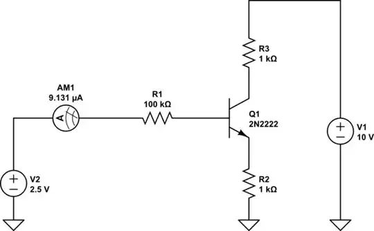
Just looking at the schematic, the collector current will be a bit less than 2mA before correcting for drop across Rb. If that transistor is a 2N2222A hFE should be between 50 and 300 so base current would be around 7 to 40uA, before correction. So 20uA isn't really out of line.
Here's a simulation, result is 9uA Ib.
simulate this circuit – Schematic created using CircuitLab
For info about internal resistance, https://www.eeeguide.com/series-resistance-microammeter/
Just verify if it is easier ... measure directly ib, or v(Rb)/100k?

If you reversed the BJT, then you are "right"!

so it might be an invalid transistor connection. So, you are right ! +1.
– Antonio51 May 12 '22 at 20:45