2

There is a universal method for determining voltages and currents in a linear circuit - that is, a circuit containing resistors, inductors, capacitors and op-amps.

  1. Laplace transfrom the input source, the inductors and the capacitors.
  2. Write a node equation for each node in the circuit.
  3. Solve the system of equations with respect to the unknown voltages.
  4. Inverse-Laplace transform the expression for the voltage you are interested in.

Here is an example of @Jonk using that algorithm to find the output voltage of an RL-circuit.

But this algorithm cannot be used on non-linear circuits. Consider a generic flyback converter shown below: -

schematic

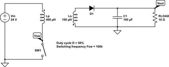
simulate this circuit – Schematic created using CircuitLab

Due to the switch (actually a MOSFET) and the diode the node equations cannot be written up in the usual way. But say I wanted to plot the voltage waveforms for the load voltage (\$V_{out} \$) and the voltage across the switch (\$V_{sw}\$) how would I do that? Can I arrive at an/a piecewise equation for both voltages?

Carl
  • 3,975
  • 1
  • 16
  • 40
  • The flyback converter transformer dots are incorrect. Why is using a simulator inappropriate here? You can use my ideal flyback tool if it helps figure out things. – Andy aka Apr 29 '22 at 11:52
  • 2
    @Andyaka The phase dots on the transformer should be correct now. There is nothing wrong with using a simulator here and I have used it before - but it is very easy to get garbage out from the simulator (if your input is garbage). Therefore, I want an analytical method for non-linear circuit analysis, if one exists, that is. – Carl Apr 29 '22 at 12:00
  • There is no method that is generic that I know of. – Andy aka Apr 29 '22 at 12:02
  • There's one perfect computation method for this. It does not unfortunately write a general result with letters and symbols, it works only if all components are exactly specified - for ex. C1=10uF, not a variable named to C1. The method=analog computing. That's building a circuit (=analog circuit) which obeys the same math law and measuring the voltages and currents from it. I see you already know one analog circuit. –  Apr 29 '22 at 12:22
  • You must add all of them. After doing it there's your analog circuit that can be built and measured. –  Apr 29 '22 at 12:34
  • Use the Shockley diode equation for a diode. – Jun Seo-He Apr 29 '22 at 13:42
  • 1
    I'm not sure it would be practical to try computing operation by hand. It first seems like it might be possible, because there are only 5 components. But most of them introduce very non-linear and step-dependent behavior, which would make any one formula (unless exceedingly complex) only an approximation at best, and downright wrong at worst. – rdtsc Apr 29 '22 at 13:48
  • @Carl with those values (and an ideal diode), Vout will be 12 volts and it will be operating in continuous conduction mode with a primary current peak of 1.35 amps and a valley of 1.05 amps. Average input current will be 600 mA. Everything ideal though. Vout ripple will be around 60 mV p-p and Vsw will be a maximum of 48 volts (assuming perfect transformer coupling). – Andy aka Apr 29 '22 at 14:03
  • Thanks @Andyaka but I’m also interested in the voltage waveforms. – Carl Apr 29 '22 at 14:52
  • Note that the primary side is undefined at the instant of turn-off, unless k=1 (k is not defined), or the switch is defined. (An ideal switch cannot exist of course, and choosing a real mechanical switch or MOSFET for example will satisfy this.) – Tim Williams Apr 29 '22 at 16:57
  • @Carl You will need a proper model for everything. Your primary side inductor, for example, includes resistance (lumped in series, usually) and capacitance (lumped in parallel, usually.) Similarly, diodes have bulk impedance (lumped in series) at a minimum and may also require charge storage (which is probably poorly handled as a capacitance and is hard to handle more exactly.) So how close to reality are you shooting for, assuming you have accurate modeling developed by testing each part you might actually use? And are you familiar with Python? (It's very easy to use.) – jonk Apr 29 '22 at 21:47
  • @jonk Can't I consider everything ideal? In forward bias the diode is a short, in reverse it's an open circuit. Same goes for the MOSFET (switch). So I'm interested in the ideal case. Also, I haven't used Python or SymPy, but I have some mathematical software called Maple that can be used to solve systems of equations. – Carl Apr 30 '22 at 06:56
  • @Carl You can't connect two ideal voltage sources in parallel (except in a trivial case.) Similarly, you can't connect an inductor in series with a current source (except in a trivial initial conditions case.) I didn't know you wanted to analyze things ideally. Since I appear to be confused about exactly what a useful answer might look like, it's probably better I bow out and leave it to others who understand things better than I do. – jonk Apr 30 '22 at 07:08

1 Answers1

2

Due to the switch (actually a MOSFET) and the diode the node equations cannot be written up in the usual way.

Sure they can.

For example, the current through the diode branch can be written as $$I = I_s\left(\exp\frac{qV}{nRT}-1\right)$$

Since this gives the current through the branch as a function of the nodes it connects to (the \$V\$ in the formula is \$V_a - V_b\$ where a and b are the two nodes involved), we can write node equations for those nodes.

So we certainly can write a set of node equations for this circuit.

The problem is they are nonlinear equations, so we have to use a nonlinear solver instead of just inverting a matrix to solve the system.

Can I arrive at an/a piecewise equation for both voltages?

Sure, that would be one simple way to solve the nonlinear equations. Change each nonlinear term to a piecewise linear (PWL) approximate equation, guess which operating region each PWL element is in, solve, and check for self-consistency. If the result isn't self-consistent, guess again about the operating states and repeat.

A more typical way (but still fairly simple) is to use Newton's method.

Commercial circuit simulators will use more sophisticated solvers, but they still start by finding the node equations for the nonlinear circuit.

The Photon
  • 129,671
  • 3
  • 164
  • 309