7

How would you go about simplifying this circuit down to a single resistor? It’s Learning assesment E2.23 in "Basic engineering circuit analysis (Ed. 10 & 11)"

I have found out, that the current dosent just go down the path without the resistor, since it splits. But I don’t have an idea for how to simplify it, due to way the resistors are placed. I guess the 10k and 4k resistors arent in series?

The circuit

Attempted solution (current source removed): Attempted solution

V_0 using previously attempted solution: enter image description here

I get a voltage of 58.87V and it should be 60V

Edit: So this is my attempt at a redraw and I think I have gotten all the nodes right, im a little unsure about node "D", since R3 isnt connected in the same manner as the original circuit enter image description here

EDIT: For the sake of completion, here is my complete simplification, with huge help from @Niel_UK Full simplification From @Niel_UK enter image description here

Bertram
  • 73
  • 7
  • Welcome! What have you tried so far? Can you draw it in another way you are more familiar with, or just a part of the circuit. – winny Apr 11 '22 at 17:02
  • I have tried to combine the 12k and 6k resistors as parallel resistors, but from there I dont know what else to do. I think, that it isnt possible to combine the new parallel resistor and the 10k resistor, since the current source is between them.

    I guess I could redraw it with the middle part to the left, and then combine the 4k and 12k as parallel?

    – Bertram Apr 11 '22 at 17:05
  • I’m voting to close this question because homework needs an attempt at a solution – Voltage Spike Apr 11 '22 at 17:07
  • Delete the current source and place an open connection there instead. Do you see anything more you can do with the remaining resistor network? – winny Apr 11 '22 at 17:08
  • Well, if I can just remove it and add a open circuit, then the 10k and 4k resistors are in series and then in parallel with the 4k. And the 6k would be in parallel with the 12k and they would be in parallel with the lefthand side, thereby creating a single resistor. Is that correct? Do I thereafter just insert the current source again? – Bertram Apr 11 '22 at 17:10
  • I haven’t calculated it, but please show it by editing your question and ass your attempted solution. – winny Apr 11 '22 at 17:17
  • You can't do it like that, since the current source is connected to the junction of the 10K and 4K resistors. – GodJihyo Apr 11 '22 at 17:52
  • I thought I could do that, based on @winny comment. How should I go about it otherwise? – Bertram Apr 11 '22 at 17:58
  • You reduced the 6k and 12k to 4k, but look how you have it in your second drawing, you have a short across it, does that seem right? You need to reduce the parallel resistances, but put the resulting resistances in the circuit properly. It's hard to visualize, so you have to pay close attention. It's reducible down to a single resistor and current source which will get you V0, then using that you can go back to the intermediate steps to find V1. The answers are shown in the problem so you can check if you've done it right. – GodJihyo Apr 11 '22 at 18:18
  • Im sorry, but I do not understand what you are trying to say. The 6k and 12k in parallel is correct, but everything from thereon is incorrect?

    So how would I reduce the left-hand side? I must be misinterpreting your answer, sorry.

    – Bertram Apr 11 '22 at 18:22
  • 2
    (Question re-opened after OP added their own attempt.) – SamGibson Apr 11 '22 at 18:26
  • @Bertram When you reduced those to 4k you put that where the 12K was, but then you shorted the 6k. So you basically took two parallel resistors, computed the equivalent value, replaced them with that value, and then put a short circuit across it. Fix that problem and then see if there is another parallel combination that you can combine. The math for this is easy, it's seeing which resistors to combine that you need to learn to do, that's what these sort of problems are designed to teach you. – GodJihyo Apr 11 '22 at 18:48
  • 5
    A good start. But try to keep those top and bottom bus lines straight. Do you see that C and D are the same node. Remember the connectivity of a 'dot' is the same as a 'line'. They both mean connection, a single node. The original question used long lines to confuse you. Try to keep those lines straight to avoid confusion. Move node D up so it's on the same top line as C. Then you'll find that R1, R4 and R5 are all in parallel, and R3 is directly across the current source. They were all along of course. But redrawing them this way makes it more obvious. – Neil_UK Apr 11 '22 at 20:25

1 Answers1

16

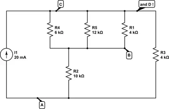
At the moment, you have a network of devices, with a random node drawn at the top, and another random node drawn at the bottom, with the current source hanging across the middle. It's drawn to confuse.

Letter all the nodes, so you don't drop any in the redrawing.

First put in your current source, and draw a bus line across the top, and the bottom, like this. I've started by putting in the 6k resistor.

schematic

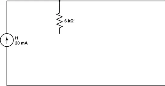
simulate this circuit – Schematic created using CircuitLab

Now draw in all the remaining components. You should find it pretty much solves itself, just for being redrawn.

Often a circuit that looks complicated is much tidier from a different view.

The whole point of a schematic is that it tells a story. The shape of the story that engineers like to see is positive at the top, negative at the bottom, current flowing down the page.

Edit following the OP's good attempt

I apologise for not having mentioned reference designators at the outset of my answer, especially as two of the resistors have the same value. Fortunately the OP was smart enough to put them in to his schematics.

Redrawing the OP's redrawing. C and D are the same node, so we need to move the D line up to C, and flip R1 and R5 round. Now it's clearly obvious which resistors are to be grouped and how they should be grouped.

schematic

simulate this circuit

The benefit of 'positive at the top, negative at the bottom' is most shown when we make the natural extension to 'decreasing voltage down the page', and 'equipotientals across the page'. It naturally places resistors that should be paralleled in parallel, and similarly for series.

On reflection, there is a more systematic way to do this redrawing. Starting with the original drawing, identify the nodes by colouring them in, like this. Remember a node is not just a dot, it's also a line or wire between dots. All of the node is at the same voltage. If you're going into a paper-based exam, I would strongly recommend taking in some old technology like coloured pencils.

enter image description here

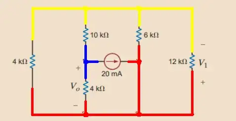
It's apparent now that there are only three nodes, and two of them belong to the current source, leaving just one additional node at an intermediate potential. It's also very easy to compare the original and redrawn circuits for equivalence. C and D are red, A is blue, B is yellow.

Neil_UK
  • 166,079
  • 3
  • 185
  • 408
  • 1
    The 10k and 6k+12k+4k are in series, because the 10k is connected to the blue node? If the 10k resistor was connected to the red node (perhaps if there werent the 4k (V_0) resistor), it would be in series with the other three? – Bertram Apr 12 '22 at 13:12
  • 2
    @Bertram Colouring in the nodes is mainly to help you make the redraw without error to get to my second diagram. From that it's clear that R1,4,5 are parallel, which are then in series with R2, which whole lot is now in parallel with R3. Just checked on a calculator and yes, that all comes to 3k, for the -60 V answer. I wouldn't try to figure out which resistors are series and parallel from the coloured schematic, I'm not clever enough, I'm sure I'd make a mistake. But from the redraw, it's obvious. – Neil_UK Apr 12 '22 at 13:23
  • 1
    I see now. Thank you so much! – Bertram Apr 12 '22 at 13:48