4

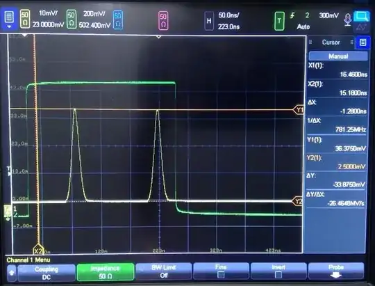
I have an expensive arbitrary waveform generator (AWG) that can create very clean arbitrary pulses. I am producing gaussian pulses from this AWG that are about 10ns wide, which look like this on a scope:

enter image description here

The AWG has the drawback of only being able to output small voltages.

I would like to cleanly amplify this signal that has a peak of 33mV to 900mV.

Right now I am using this amplifier to amplify the signal. The output looks like:

enter image description here

As you can see, there is a considerable amount of ringing on the signal at the end of the pulse.

I think it's possible that I can fiddle with the amplifier settings to try to get some level of improvement. I am considering how reasonable it would be to get a new amplifier.

  • Are there devices that can amplify this kind of signal without this ringing effect?
  • How do I evaluate from the datasheet of my amplifier what it should be able to do theoretically?

The datasheet of the amplifier says the following:

enter image description here

Is this % overshoot/undershoot the parameter that I should be paying attention to for the amount of ringing? Is this saying that the ringing is a 5% overshoot from the target value of zero?

EDIT: User Kuba asked for some context to this use case, since in many applications the actual ringing effect is not so important to remove.

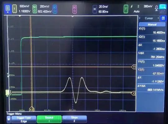
These 10ns pulses are sent into an electro-optical modulator to carve this shapes out of pulses of light, which are used in an experiment. In addition to carving 10ns gaussian pulses, I also carve other "hermite gauss modes." A gaussian is a Hermite-gauss mode of n = 0. On the scope, the Hermite Gaussian mode of 2 looks like:

enter image description here

The goal (and reason for choosing different hermite-modes) is to create a set of temporally-orthognal pulses, such that the area under the curve of the combined fields is zero. $$ \int E_1(t) E_2(t) dt = 0$$

Here you can see the effect of the ringing on a histogram of the optical light: enter image description here
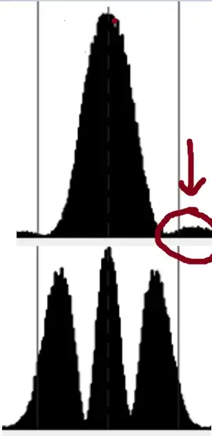
So you can see that with the different functions, there is a bit of unwanted overlap. I'm not sure if this is enough to explain my issue, but it is something that I think might be possible to remove.
Steven Sagona
  • 229
  • 1
  • 6
  • 1
    What's the GBW product of the amplifier? What's your layout and decoupling situation? What's the load? – winny Apr 07 '22 at 15:34
  • 1
    You haven't given a schematic for your amplifier setup. Does the amplifier have a negative voltage rail (or a voltage supply below the minimum input/output voltage)? – W5VO Apr 07 '22 at 15:39
  • 1
    I assume that you've provided a positive and a negative power supply rail, as mentioned in the datasheet. Makes me wonder what the crossing point is about, and if the DC bias setting has any effect on that transient "ringing" behavior. As per datasheet, the DC bias appears to be something marginal on the output, facing the "load". The amp is DC-coupled on input and output? (as opposed to AC-coupled) – frr Apr 07 '22 at 15:47
  • 2
    Such amplifiers are designed with a particular application in mind, since an "ideal" amplifier is not feasible. What is your application for those 900mV gaussian pulses? Ringing is not the only parameter. It's a tradeoff. What jitter do you need? Amplitude stability/repeatability? Etc... It may turn out that ringing is not very important in your application. Getting rid of ringing at these timescales is expensive, and it's not only about the amplifier but also about the connections - quality of cables, connectors, matching of the load impedance, etc. Physical layout of your measurement setup! – Kuba hasn't forgotten Monica Apr 07 '22 at 16:01
  • Thanks for the comments. I'll try to answer them individually. – Steven Sagona Apr 07 '22 at 16:18
  • @winny, sorry a bit too technical for me. Are these properties that you would like me to measure? Is this not something that would be provided/inferred in the linked datasheet? – Steven Sagona Apr 07 '22 at 16:20
  • @W5VO, are you asking me to provide the voltage values I have chosen for the different pins of the amplifier? That I can provide. – Steven Sagona Apr 07 '22 at 16:20
  • @frr, yes, I've struggled to interpret what some of these values mean, such as the crossing point. Changing it doesn't appear to do much in my case at the moment. – Steven Sagona Apr 07 '22 at 16:22
  • @Kubahasn'tforgottenMonica, I added a section to the question explaning the context of what I want them for. "What jitter do you need?" - sorry what is jitter exactly? is it the amount of variation there can be in the time of arrival of the signal? if so, then ideally something like 1% of the pulse width, so 100ps or better. "Amplitude stability/repeatability?" Not super important, maybe 5%. – Steven Sagona Apr 07 '22 at 16:46
  • If you use a 10:1 probe, read the datasheet of the probe very carefully. Try to connect the generator to the oscilloscope using a 50 Ohm output and input. Then try to connect the scope to the generator via a 10:1 probe. If you cant avoid ringing when using the probe at the generator, you got no chance at the output of your amplifier. – Uwe Apr 07 '22 at 17:24
  • @Uwe, sorry having some trouble with the termology. What do you mean by the "probe" and "generator"? Is the probe the small signal that I want to amplify? (if so there is a picture of it on the scope in the question which see's no ringing) – Steven Sagona Apr 07 '22 at 18:21
  • Oh! It’s a standalone product, not something you implemented. Then you can’t do much about it. – winny Apr 07 '22 at 18:35
  • For a 10:1 probe have a look here https://www.tek.com/en/datasheet/500-mhz-passive-probes With generator I mean your " expensive arbitrary waveform generator (AWG)" – Uwe Apr 07 '22 at 20:03
  • @Uwe, ok so even though my generator clearly can produce these signals without any ringing (when seen with a 50 Ohm internal resistance scope), you're saying that I can do this other sort of diagnostic tool to evaluate if my generator is capable of being amplified? I guess I'm missing the point if it seems like on a scope I can see that it doesn't exhibit this ringing preamplification. – Steven Sagona Apr 07 '22 at 23:56

2 Answers2

2

I cannot see your layout, but the tail resonance appears to be ~ 60 ns or ~ 17 MHz which could be the self resonance frequency of your 10:1 probe length or trace inductance or excessive high impedance tracks (~1nH/mm) and coax capacitance (~ 70 pF/m ) or trace capacitance less depending on W/g ratio of conductors.

An impedance matched voltage divider with good coax (semi-rigid) terminated in 50R will give textbook waveforms for this spectrum assuming return loss is > 15 dB.

Your physical connectors are important. Unless you have high-grade coax, use semi-rigid coax and adapters to keep short. enter image description here

Understand every conductor has capacitance and matched impedance is required over the entire spectrum based on root of L/C ratio. If you define everything then we can understand better.

Tony Stewart EE75
  • 1
  • 3
  • 54
  • 185
  • what do you mean by layout? Is there more information you would like me to provide? I an probably do so, but I'm not exactly sure what additional info you would like. Sorry, as you can see I haven't yet learned all the electronics lingo. – Steven Sagona Apr 07 '22 at 18:24
  • Ask for the torque gauge for help – Tony Stewart EE75 Apr 07 '22 at 20:30
  • So the main thing that you would like to be specified is the exact torque I have applied to my SMA cables? But overall you want me to make more clear what cabeling is being used? – Steven Sagona Apr 08 '22 at 16:30
  • The main thing is realistic specs for impedance matching and consequences of mismatch but you ought to show a photo of you connectors. Finally SMA torque is important to know. LEarn it. – Tony Stewart EE75 Apr 08 '22 at 21:39
1

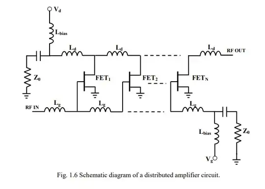
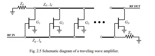
If one wants to keep the "shape" of the pulses,
it would "be" better to use a "distributed" amplifier,
with the essential characteristic of a constant "group delay" time.

From this

enter image description here

Or simply ...

enter image description here

Antonio51
  • 13,128
  • 1
  • 7
  • 22
  • Thank you for your answer. Do you happen to know of any commercial products that fit my need? Doing some googling I see some things labeled as distributed amplifiers, but I'm not sure how to interpret some of the specs. For example, this one lists min and max frequency. Any idea what I would want here for my situation? – Steven Sagona Apr 07 '22 at 18:31
  • There are in fact 2 problems, "perhaps", the first is that some of these amplifiers are not DC coupled ... the second is that the "group delay" is not mentioned or specified. If you have the "technical manual" of the AWG, first, try to see "how" the "output amplifier" is designed (I think it is DC coupled). – Antonio51 Apr 07 '22 at 18:59
  • Another option: trying it ... if the price is affordable. Probably could be working DC with some cautions. – Antonio51 Apr 07 '22 at 19:13