I tried changing up the power supply. I tried 15 V, and one with a higher current rating (8 A). Here is the datasheet of the I have been mainly using: EPP-200 24 (volts).
There are two stepper motors run by two drivers:
- DRV8825 Stepper Motor Driver datasheet
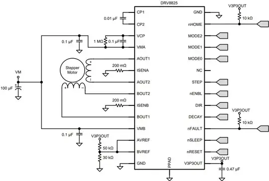
I have adjusted the current limiting resistors (50k and 30k). I need the torque by using 20k and 30k voltage divider:
Both 0.1uF and both 10kΩ components are crossed off because I did not include them in the design. Here is the original circuit from the datasheet:
Using the modified circuit (20k and 30k resistor biasing), one of the motors stops moving after 70 seconds. At higher current (higher torque), one of the stepper motors stops moving more quickly and the second motor within minutes also stops working. By "stops working" I mean there is no holding torque.
From the datasheet, this looks like overcurrent protection is occurring since the motors do not resume running (and some of the test they stopped moving just being warm to the touch, not hot).
- NEMA 23 motors datasheet
https://www.omc-stepperonline.com/nema-23-stepper-motor
(I do not know exactly which NEMA 23, but I can find out...)
To troubleshoot, I have also changed the motors out to higher precision NEMA 23 motors. Should some sort of diode be put between the power supply or between the voltage regulator and ESP32?
MCU - ESP-32 datasheet
It seems to run fine (indefinitely) when the ESP32 is powered by USB and at low torque. Although, I need high torque for my application. I have refined the current vs torque, with less torque (and less current), but it is still high enough current where the motors stop moving and do not resume.
This is the ESP/Arduino program. It is fine. I'm just including it for those who will ask for it anyway.
const int dirPinX = 0;
const int stepPinX = 2;
const int dirPinY = 19;
const int stepPinY = 18;
void setup()
{
  Serial.begin(115200);
  delay(500);
pinMode(stepPinX, OUTPUT);
  pinMode(dirPinX, OUTPUT);

  pinMode(stepPinY, OUTPUT);
  pinMode(dirPinY, OUTPUT);
}
void loop()
{
for(int i = 0; i < 600; i++)
  {  // Set motor direction clockwise
    digitalWrite(dirPinX, LOW);
    digitalWrite(dirPinY, LOW);
if(i%2)
  stepX();

stepY();

}
for(int i = 0; i < 600; i++)
  {
    digitalWrite(dirPinY, HIGH);
if(i%2)
  stepX();

stepY();

}
  delay(100);
}
void stepX()
{
  digitalWrite(stepPinX, HIGH);
  delayMicroseconds(200);
  digitalWrite(stepPinX, LOW);
  delayMicroseconds(200);
}
void stepY()
{
  digitalWrite(stepPinY, HIGH);
  delayMicroseconds(200);
  digitalWrite(stepPinY, LOW);
  delayMicroseconds(200);
}
Related
When driving stepper motors do i need to worry about back EMF?
https://e2e.ti.com/support/motor-drivers-group/motor-drivers/f/motor-drivers-forum/107329/drv8825-overcurrent-protection-issues (In my setup, it is set to mixed decay mode or floating pin.)

