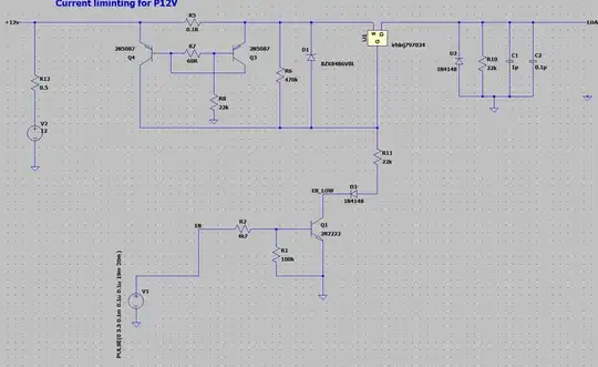
I got a circuit from a current limiter for 12V by using a P-MOS, this is apply at the output from a DC/DC converter, I have to limit the current for 5 different voltages. I want to understand how the circuit with the PNP are working and how I can limit the current of the 12V. It would be great if somebody can help me.
Asked
Active
Viewed 265 times
1
-
It's an interesting transistor circuit. The PNP pair forms obviously a PNP current mirror and the resistor divider in the middle somehow alter the behaviour (probably some compensation). https://wiki.analog.com/university/courses/electronics/text/chapter-11 explains the working. The mirrored current pulls up the gate of the MOSFET thus limiting the current (the mosfet will heat up) – Lorenzo Marcantonio Mar 16 '22 at 14:02
-
By the way it's fully floating so it shouldn't matter the voltage you apply – Lorenzo Marcantonio Mar 16 '22 at 14:02
-
Thanks Lorenzo for your answer, I will have a look to this documentation! – Taru WRC Mar 16 '22 at 14:07
-
I simulated it in spice and it doesn't seem to limit anything. Are you sure it is working and if yes if it is sketched correctly ? – tobalt Mar 16 '22 at 16:14
-
1@LorenzoMarcantonio The 68R resistor in the middle compensates for base current that would otherwise make the source asymmetric. – Kuba hasn't forgotten Monica Mar 17 '22 at 17:52
-
i knew about the 68r resistor but i've never seen the 22k to ground. Also it's mostly textbook stuff unless the BJT are matched… current mirrors and longtails are only used in IC usually – Lorenzo Marcantonio Mar 18 '22 at 07:14
-
also for me, I saw that this configuration of the 2 pnp, acts as a differential-voltage sense-amp across the resistor 0.1ohm. 68R compensate the base current, but I am still investigating what is doing this 22k resistor – Taru WRC Mar 18 '22 at 12:11
