0

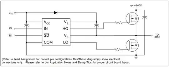
The below diagram is from the first page of the Infineon IR2104 Half-Bridge Driver datasheet.

enter image description here

I have a Vbus that is also the power source for this IC (or I want it to be).

One presumes that the LO is driven by the Vcc from here and thus at high frequency this is ~ 2 A @ the gate voltage (GanFET in my case so about 6V)

This would be simple if my VBus was say 12V. But it it's ~ 100 V. (And once I get this working at lower voltage it may go higher)

I can't find any documentation on the suggested mechanism for getting Vcc from the VBus. And all of the test reference designs use a separate power supply for this and magically power it.

So what is the recommended, most efficient way to generate the Vcc from the VBus to power this?
TonyM
  • 22,898
  • 4
  • 39
  • 64
  • Why do you assume 2A of current? The driver can only handle quite a bit less. – Lars Hankeln Mar 03 '22 at 18:28
  • I’m using that as an example but a ganfet at 132kh will use 2a quiescent current @ 6v typically and there’s 2 so really 4 amps. – James Hancock Mar 03 '22 at 19:01
  • Can you provide a link to the source of that information (datasheet or whatever)? 12W is a lot more driving power than i would expect for something like a 650V GaN transistor. I would guess < 1W – Lars Hankeln Mar 03 '22 at 19:40
  • Here's an example: https://www.ti.com/lit/ds/symlink/lmg3422r030.pdf?ts=1646251750222&ref_url=https%253A%252F%252Fwww.ti.com%252Ftool%252FTIDA-010203 - Go to page 6-8 under Buck/Boost high peak current. This one is really good at 1.2 amps. Most are in 2 amp range per, so you're at minimum 3 amp with headroom closer to 4-5 depending. – James Hancock Mar 03 '22 at 19:44
  • 1
    That is the peak current. The average power that the Vdd power supply needs to provide is a lot lower (e.g. 12V 18mA @140kHz). The peak current can be provided by capacitors at the output of the Vdd power supply. – Lars Hankeln Mar 03 '22 at 20:15
  • @LarsHankeln so an mps synchronous buck chip with 450v and 320 mA would have enough power? – James Hancock Mar 05 '22 at 17:01
  • 1
    A buck converter that can provide something like 6V 200mA from your Vbus input should be enough. – Lars Hankeln Mar 05 '22 at 17:27

1 Answers1

0

And all of the test reference designs use a separate power supply for this and magically power it.

This IC and the other similar-purpose ICs are designed to be used in HV switching circuits such as off-line bridge-type (half bridge, full bridge, LLC half bridge, etc.) converters and motor drivers. So, it's assumed that those applications already have a separate, clean, low voltage source for different purposes such as supplying control circuitry (including gate drivers), fans, indicators etc.

So what is the recommended, most efficient way to generate the Vcc from the VBus to power this?

Depending on the application, you may not need to generate Vcc from VBus. If the main application is a power supply (i.e. an AC/DC or a DC/DC converter) then you can add an aux winding to the transformer to have a low voltage source. If you have only an HV source then a buck converter might be the way to go (There are lots of buck converter ICs with internal MOSFETs having an input voltage of up to 1kV). A linear regulator can be another option but might be a bit bulky, and also powering a linear regulator from an HV source or designing a linear regulator to be supplied from an HV source is another problem.

Rohat Kılıç
  • 33,940
  • 3
  • 29
  • 85
  • 1
    The issue is that this isn't isolated. This is specifically for a DC/DC converter that will programmatically know it's input voltage and current and have the output to a DC bus defined in software (i.e. it will allow the user to set the DC Bus voltage that it will output) I will be putting in a dual power source IC to prefer bus to supply but it could be powered from the solar panels on the input which is variable based on the string length. So I can't find anything that will drive 4 A from the bus source (lots in the 500ma range) – James Hancock Mar 03 '22 at 15:41