1

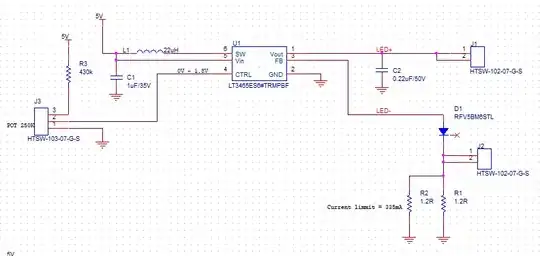
I'm looking at driving an LEDs, maximum 6 LEDs in series (can be less.)

I have used the LT3465ES6 for this job.

I have calculated the needed current limit resistor and didn't get the needed results (tested with 4 LEDs 50 mA.)

The calculation is:

enter image description here

Input voltage is 5 V.

In the schematic I have added a high current diode in case the operator shorts the LED+ and LED- signals (this is for protection, the diode acts like an LED (Vf=2.9.)

My LEDs are 2.9 V and can stand 1100 mA (I need 350 mA maximum.)

The control potentiometer is 250K ohm.

J1 and J2 are outputs for the LEDs.

enter image description here

JRE
  • 71,321
  • 10
  • 107
  • 188
Gal Magen
  • 55
  • 5
  • Some comments: D1 should be removed from the circuit. It will make the circuit non-functional since the voltage at the FB pin will be dominated by Vf of the diode. The IC will servo the output voltage so that Vfb is 0.2V. Even at very low output voltage, Vfb will be above 0.2V due to D1 causing the loop to throttle back. Also: there is no need to protect against a short, since the current is limited by the sense resistor.

    335mA is too much current since the part is not guaranteed to be able to supply that.

    – Troutdog Feb 24 '22 at 18:31
  • Your LED connection J2 is shorted. – winny Feb 24 '22 at 19:12

2 Answers2

2

There are two major issues:

  • The FB pin cannot be driven correctly because your protection diode is hooked up incorrectly.

  • The LT3465 will have difficulty driving 50mA@17.4V (6 leds) from 5V. If you take into account the stated 80% efficiency at higher loads then you start to come dangerously close the maximum internal switch current of 225mA (minimum). 335mA of led current is not going to happen. That poor IC :( A strong giveaway is that most of the performance curves are only specified up to 20mA.

Obviously the second one is most problematic and calls for a different driving solution altogether. So lets focus on the first problem which is fixable:

Again there are two issues here.

  • You mention that the diode is supposed to act as another LED. While this would be mildly effective, you haven't wired up your schematic accordingly. The net that the Fb pin connects to is called Led-, but the connector for the leds is actually connected below this net, bypassing the diode that you intended for protection completely. Did you intend to put the negative led connector above this diode instead?
  • Because of this the diode is actually blocking the shunt voltage that the led driver needs to regulate its output. That's no good.

The Fb pin has an absolute maximum rating of 2V, while it's normal working voltage is 0.2V. That means if you want to protect it you could indeed use a diode, but you would have to arrange it in a different way to be effective. Like mentioned, now it is preventing the Fb pin from taking proper measurements.

You can either:

  • clamp the voltage across the sense resistor with a diode so that the voltage across the shunt will not go above about 1V or so. At 0.2V (normal shunt voltage during regulated operation) a regular diode would not conduct much at all. Any leakage would be much much lower than the normal shunt current and thus not impact the accuracy at all.

  • place a series resistor in-between the high-side of the shunt and the feedback pin of the driver. Now this Fb node can be protected with a diode towards ground, set to conduct as soon as the Fb pin goes above 0.6V or so. The series resistor is there to limit the current when this happens. Don't select the series resistance too high, because of noise and offset concerns.

Thijs
  • 614
  • 3
  • 7
  • you though correctly, the anode of the diode needs to be on the LED+ and J1 needs to be at the cathode so it will act as an LED in case of shorting J1 and J2 – Gal Magen Feb 24 '22 at 18:31
  • which drive method you can suggest for driving 6 LEDs with 350 mA ? – Gal Magen Feb 24 '22 at 18:33
  • This could work: https://www.ti.com/lit/ds/symlink/lm3410.pdf?ts=1645773522124 They still have stock :) Also read this: https://www.ti.com/lit/an/snva253a/snva253a.pdf And be aware that even the more generic boost converter ic's can be given some form of current feedback. I did so plenty of times with simple shunts and difference amplifiers. More difficult then off-the-shelf but sometimes worth it. Be sure to compensate the loop accordingly if needed. Read: https://www.ti.com/lit/an/snva829/snva829.pdf – Thijs Feb 25 '22 at 09:21
0

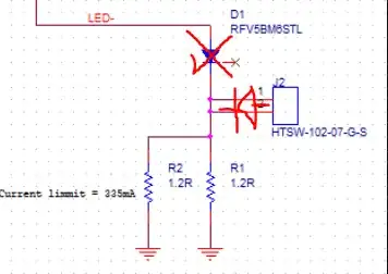
It's most likely D1. Had a brief look at the datasheet, and D1 will probably cause issues with the feedback circuit internal to the IC... I also don't quite see how the diode will protect in this configuration, as the diode anode should be in series with the other LEDs if you want that kind of behaviour. I would rather put the diode between J2 and LED- nodes, with anode connected to J2, and then FB needs to be directly connected to the resistors...

Something like this: enter image description here

TheMAX135
  • 147
  • 6