2

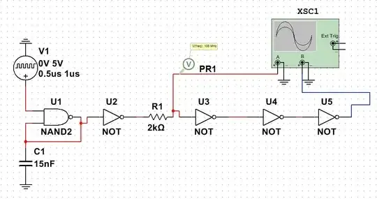
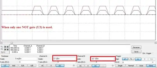
I'm modulating the message signal with OOK (on-off keying) modulation. Multisim software is used to model the schematic [attached]. At the resistor R1, the modulated signal is obtained. I wanted to invert the modulated single, for that I used a simple NOT gate (U3), however at the NOT's gate output, I got the same signal as input means without inverting [attached]. So my question is, why isn't the NOT gate inverting? Am I doing something wrong?

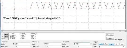
As hit and trail, I added two more NOT gates (U4 and U5) but this time I got an inverted signal, although further improvement is needed to achieve a 180-degree phase shift. So my second question is: Why is it an inverter this time? and how to get exactly a 180-degree phase shift between two signals?
Thanks for your time. enter image description here enter image description here enter image description here

Bam_Khel
  • 81
  • 6
  • 1
    Have you considered the inverter's propagation delay? – Andy aka Feb 15 '22 at 15:17
  • 1
    Do you want to invert your output (logical NOT) or add a 180-degree phase shift to it? They are not the same, although it may appear so when you are working with a 50% duty cycle square wave. – Prathik Prashanth Feb 15 '22 at 15:29
  • @PrathikPrashanth I am inverting the output. and the duty cycle if the input is 50% so in this case, both are the same. – Bam_Khel Feb 15 '22 at 15:36

1 Answers1

0

You don't give a part number for the NAND gate, so we don't know if it has hysteretic inputs. And, usually there is a resistor in the feedback path for more control and stability of the oscillating frequency.

Beyond all of that, the oscillator probably is producing a symmetrical output, which looks the same on a scope inverted or not because of how a scope trigger works. The extra inverters are merely a delay line, giving a time-shifted (not inverted) image.

What is the purpose of R1?

AnalogKid
  • 19,998
  • 1
  • 13
  • 32