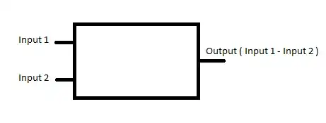
Is it possible to create a blackbox that is defined with an equation in Ltspice. Something like this:

- 96
- 10
2 Answers
I haven't used LTspice to know if you can do "black boxes" defined by equation (you can do sub-circuits, and then view those as black boxes if you wish, in your case you might look into op-amp based substractors, or into using a controled voltage source).
But in any case, there is no way you could define a black box like your example (in any software I believe, excepted it it makes some assumptions that are not explicit in your drawing) :
first, your output is not defined : you get a voltage Input1 - Input2, but without any reference point, so it don't make sense (either you take it relative to input 1 or 2, or you need to add a ground pin as reference).
second, you lack supply pins (well, that might be acceptable in a high level simulation)
last and not least, you haven't defined the currents flowing in each pin, so that makes any simulation impossible (a simulator needs to simulate voltage and current). The simplest way would be to define an imput impedance (or resistance) for each pin (nb : the second end must be connected somewhere, for example the missing ground pin). If you want an "ideal" commponent, you could define infinite input impedance, and 0 output resistance.
EDIT : I think to I have found the solution : your can use "arbitrary behavioral voltage sources" : you can have a voltage related with nearly any expression to any voltages/currents in your simulation. This is enough for your simple example.
If you want something more complexe, use a sub-component in which you put your arbitrary behavioral voltage source and the input/output impedances you need.
For more informations about arbitrary behavioral voltage sources, you can have a look at this tutorial from LT
- 7,277
- 11
- 37
-
Image is purely an example.. there was an answer here that was deleted for some reason. – Hedgehog Jan 31 '22 at 18:19
It depends on what you want.
If you are talking about making a subcircuit for a block, you can create your own graphical symbols from subcircuits: https://www.youtube.com/watch?v=bOzKJr62Uc8
If you are talking about a black box that no one can see the inside, LT spice offers a way to encrypt subcircuits. Create a sub-circuit, then encrypt it. You can pass The instructions to do so are located here:
How to create encrypted spice subcircuit/schematic and use it as symbol in other schematics?
- 82,181
- 41
- 84
- 220
.paramwas off, which could have been omitted. – a concerned citizen Jan 31 '22 at 20:45