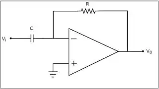
But an op-amp differentiator, like the one in the figure below, is certainly realizable
Yes, it is
and has a TF of the form \$G(s) = -RCs\$
Generally not.
You're using the method where you set \$V_- = V_+\$ and solve for the transfer function. That method is only valid if the resulting circuit happens to be stable.
A more realistic method sets \$V_o = A(s) \left(V_+ - V_- \right)\$, calculates \$V_-\$ (and \$V_+\$ if necessary) as a function of \$V_o\$, and solves the resulting feedback equation. In this case, for most internally compensated, unity-gain-stable op-amps, our "more realistic" \$A(s)\$ is something like
$$A(s) = \frac{A_{GBW} \omega_0}{s \left(s + \omega_0 \right)}$$
where \$A_{GBW}\$ is the gain-bandwidth product of the op-amp in radians per second, and the manufacturer has chosen \$\omega_0\$ for stability, probably setting it in the range \$\frac{A_{GBW}}{5} < \omega_0 < \frac{A_{GBW}}{2}\$, depending on how sporting they want to be with overshoot and stability.
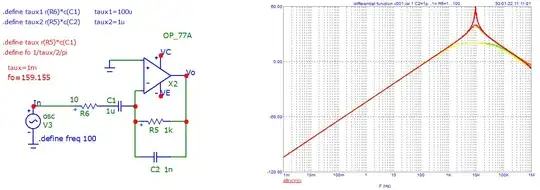
If you grind through all the math, you'll find out that for your circuit, with "sensible" component values (i.e. \$R\$ matches the op-amp's capabilities, so probably around \$1\mathrm k \Omega \le R \le 1\mathrm M\Omega\$, and \$\frac{1}{RC}\$ is well within the gain bandwidth product, your circuit is unstable, or at least shows a very strong resonance, with a little bit of differentiator action thrown in.
Trying to actually wire up that circuit and seeing the result was one of my first practical introductions to the joys of trying to make op-amps do what the simplistic theory seems to say they can.

