When you start running these KBP310 bridge rectifiers in parallel the Vf goes down. Anyone know why that would be?
The basic diode (or Shockley) equation explains why: -
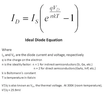
Image from here.
So, if the current through a diode is shared between two diodes then \$I_D\$ drops to half. So then, if you re-arrange the formula to solve for \$V_D\$ you will see that \$V_D\$ drops a little bit for a halving the diode current \$I_D\$. You probably thought that all diodes drop a fixed forward voltage irrespective of forward current? Not true. Reality is more complex.
I noticed when you start running these KBP310 bridge rectifiers in
parallel the Vf goes down. From .998v for 1 to .900v for \$\color{blue}{\boxed{\text{X4}}}\$ bridge
rectifiers together
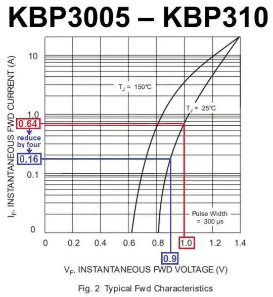
Image from here.
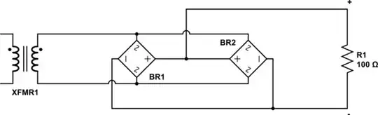
I was thinking if you run 2 chips in parallel but reverse the A/C
leads on the second one would that lower ripple and maybe Vf a little
because the rectifiers would be out of phase with each other?
No, it won't make the slightest difference.


Note that when you use the CircuitLab button on the editor toolbar and Save and Insert on the editor an editable schematic is saved in your post. That makes it easy for us to copy and edit in our answers. You don't need a CircuitLab account, no screengrabs, no image uploads, no background grid.
– Transistor Jan 09 '22 at 15:03