3

I am trying to build a circuit design that has 4 LEDs that will need more current than the ATmega328 can give out. I will want the LEDs in parallel so I can control them all individually. Because they are higher current LEDs, I will be using a simple constant current driver using a transistor, FET, and resistor. I have attached the link below for reference. The problem is that I will need 1 current driver per LED. This will add cost and space on my PCB. I am wondering if anyone can help me figure out a way to simplify this down so I can keep the cost down and have my PCB take up less space.

Constant Current Driver: http://lednique.com/power-supplies/simple-constant-current-driver/
Myles
  • 31
  • 3

2 Answers2

2

I'm going to assume that you need individual high-current control over each LED, and that more than one LED can be on at a time. This rules out using a shared current source for all the LEDs.

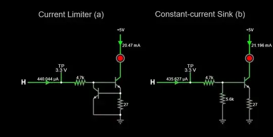
There's a solution that I think will work for you: dual NPN packages in SOT23-6. These take about the same space as a single SOT-23. You can make a current limiter with just one SOT-23 package and two resistors per LED. Example: https://www.onsemi.com/products/discrete-power-modules/general-purpose-and-low-vcesat-transistors/mbt3904dw1/

Another solution is to use a cheap-o constant-current sink.

Here is a sim of both the current-limiter and current-sink approaches (simulate it here)

enter image description here

Circuit (a) uses amplified feedback from the sense resistor. It's pretty accurate. Circuit (b) works as an emitter-follower, using the sense resistor as feedback to set the follow voltage, and thus, the LED current. This is more economical.

Your other option is to just use a resistor per LED and some sort of open-drain / open collector driver. This of course has the issue of Vf variation affecting brightness, which can be dealt with by using 'binned' LEDs with matched (or at least consistent) Vf.

hacktastical
  • 53,912
  • 2
  • 49
  • 152
  • Circuit (a) is what I was trying to avoid, but with the dual NPN package, that could help with saving room. Can you explain how your circuit (b) works a little more and what is cons are compared to circuit (a)? – Myles Jan 11 '22 at 16:55
  • Circuit (b) is an emitter-follower, so will tend to hold the voltage across the emitter resistor at one Vbe drop below the base voltage. It is somewhat more sensitive to transistor beta variation than (a). – hacktastical Jan 11 '22 at 17:16
  • Thank you. I appreciate it. – Myles Jan 11 '22 at 18:31
1

One solution to use less components/pay less would be to use one resistor in series to limit current to the maximal allowed one, and to use a MOSFET to switch each one on and off (if you use a PWM pin, you can change the luinosity of the led).

Note that with this solution you don't get as precise current control as with a LED driver, but it is simpler

Sandro
  • 7,277
  • 11
  • 37