3

I am working at a LM317 power supply (tracking pre regulator) and I found on the internet a schematic for overload indicator, which I added into my simulation and into my test circuit.

After simulating, I found that the Base current of Q9 has spikes of about 4.5-5A, which I think that is very high for a BC327. By adding a 100R (R26) resistor into Q9's base results into a lower value current. Please find below the schematic of the circuit and the simulation results (1st result is with R26=100R and 2nd with R26=0R).

Are any other modifications needed ? Can R26 resistor value be as high as 1k ?
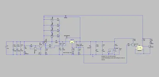
schematic

R26 = 100R

R26 = 0 R

Voltage Spike
  • 82,181
  • 41
  • 84
  • 220
beard999
  • 333
  • 1
  • 6
  • 21
  • 1
    Where is the output of the power supply supposed to be? If it's the output of the LM317 the design makes little sense: you parallel 4 2N3055, which have a max current of 15A, for a 60A max. Even assuming you run them at 10% load, that makes a 6A capable preregulator stage feeding a 1.5A max device (LM317). The preregulator seems utterly oversized. Do you have some design notes about that circuit? Or did you pick up a random schematic on the Internet? – LorenzoDonati4Ukraine-OnStrike Dec 28 '21 at 01:36

3 Answers3

5

Its unlikely that the spikes will happen in the real world, as all wires and traces have inductance, in spice the wires are superconducting (actually, better than superconductors, real superconductors have a few nano ohms). I would first put in some resistance and inductance to simulate a wire\trace. Something like 10mΩ and 20nH and see what happens to the spikes. (you can do this with only and inductor or resistor then add parasitics to the component). I'd imagine that the spikes would attenuate significantly.

You may also want to add some series inductance to the switch, it's infinitely fast switch (well as much infinity as the simulation will allow) which is also not possible in the real world. Add series inductance to that also (Lser=100nH).

Making the circuit look more like a real world circuit with parasitics should take care of the spikes. If it doesn't and it really is the BC327-40 that is causing the spikes, you may want to add an (real) inductor in series with it.

Voltage Spike
  • 82,181
  • 41
  • 84
  • 220
1

I think the power transistors Q4, Q5, Q6, and Q7 should have their resistor emitters connected after the LM317, not before. That would explain the high current on your simulation.

VictorTito
  • 459
  • 2
  • 4
-1

This is usually done with LM431, in fact you can find the circuit that uses LM317 in LM431's datasheet, on page 7: http://www.szhuge.com/file/productpdf/1019221237830500.pdf

  • You are wrong. The circuit you refer to is a precision voltage regulator, where the LM431 is used to improve the regulation accuracy of an LM317. It doesn't work as an overload indicator at all! – LorenzoDonati4Ukraine-OnStrike Dec 27 '21 at 18:56