14

I have a digital storage oscilloscope. The probes have three options for coupling:

  1. DC
  2. AC
  3. Ground

My understanding of 1 & 2 is:

  1. DC: I connect the ground clamp of the probe to ground, the 'live' probe to the thing I'm interested in and the scope will show me an absolute potential difference between the two.
  2. AC: I connect the ground clamp of the probe to ground, the 'live' probe to the thing I'm interested in and the scope will attempt to remove the DC-ness so I just see the PD wave as if it were averaging neutral.

The ground coupling confuses me though.

  1. What's it for?
  2. When would I use it?
BanksySan
  • 333
  • 2
  • 10

3 Answers3

18

Ground coupling connects the input of the oscilloscope to ground (and disconnects the external probe). You can use it to make a trace "flatline" without having to physically disconnect the probe from the signal you're measuring. This can be useful to check or adjust the vertical offset of a trace (or any other purpose where you'd want a trace to be zero temporarily). With analog scopes, you first had to ground-couple an input before you could adjust the trace's vertical position so that it matched the grid on the screen. While this is not strictly necessary on digital scopes, they simply kept that function.

Jonathan S.
  • 18,288
  • 34
  • 56
  • 3
    I've also seen oscilloscopes automatically switch inputs to ground in case the voltage got too large, presumably in order to protect themselves from damage – Lukas Lang Dec 10 '21 at 07:18
11
  1. AC: ...the scope will attempt to remove the DC-ness so I just see the PD wave as if it were averaging neutral.

Setting the input to "AC" does nothing magical; it simply places a small capacitor in series with the input. This does have the effect of removing a DC bias, up to some low frequency, determined by the capacitance value used. Research capacitive reactance for more info.

The "Ground" input is used to temporarily disconnect the probes and set their inputs to ground. As Jonathan says, this is a legacy feature, and is rarely useful on modern scopes.

Also note, all scope ground leads are connected together, and these are also connected to the mains Earth ground. For this reason, sometimes scopes are powered from isolation transformers (to remove this Earth grounding.) Even with this, many-a-scope and circuit has been damaged from a momentary brain-slip; always be cognizant of scope grounds.

rdtsc
  • 16,238
  • 4
  • 32
  • 70
5

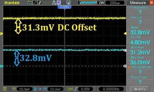
Shown below is the display of a 2-channel Digital Oscilloscope, with no probes connected to their respective inputs. Note that both channels are set to maximum sensitivity of 20mV/square.

Shown at extreme left are indicators showing where a zero-volt trace would display. As you slide vertical position up and down, these indicators move vertically. Each channel has its own arrow-like indicator (Ch.1 in yellow, Ch.2 in blue).

At the right, the oscilloscope has made measurements of Ch.2 (Blue):
Oscilloscope display, no probes


I have set cursors on channel 2 in an attempt to verify voltage measurements. Cursor measurement agrees with the Mean measure of 32.8 mV.


With no voltage going into the 'scope, you'd expect to see a display of zero volts. Instead, this oscilloscope displays an internal DC offset voltage of about +32 millivolts.

This measurement was made with the DC/AC/GND input selector set to DC
When set to GND, zero volts was displayed.
For this oscilloscope, the GND selector gives a display of zero volts as indicated by those extreme-left arrow indicators.

One wishes to ask, "Where does zero volts display?"
The extreme-left indicator displays zero volts at a different vertical position than the waveform display - this difference is a D.C. offset. So which is true zero: the indicator, or the displayed waveform?

If I were to make a critical measurement, I would subtract this DC offset of 32 mV. from every measurement this oscilloscope makes.


TLDR: For this oscilloscope, the GND position of the DC/AC/GND selector is useless, because those extreme-left channel indicators give a more-immediate display of the same information.
The GND position is a legacy left-over from older analog 'scopes that gave no indicator where zero volts would display.

After this measurement was taken, the oscilloscope was put through a self-calibration.
After self-calibration, a similar DC-offset measurement was made...
That DC-offset was calibrated out: mean voltage showed either 0.00 or +800 uV. With no input voltage, the zero-indicator and displayed waveform agreed.
A reminder to other digital 'scope users: do a self-calibration!

glen_geek
  • 25,809
  • 1
  • 23
  • 53
  • Note: the DC offset is likely to be range-dependent. It can be a bit hard to see, but if you use the integration tools built into many scopes it becomes obvious. So self-calibrate (or do an equivalent manual operation) on the right range. I was integrating very short photodiode pulses with a bit of trigger jitter, so I had a bit more integration window than I would have liked. The offset accounted for more than half the recorded pulse area until we corrected it – Chris H Dec 10 '21 at 15:34
  • @ChrisH Old analog 'scopes very often had range-dependent offsets as you've pointed out. For example, the 2:5:10:20:50:100...range sequence often showed 3 different offsets corresponding to 3 different preamp gain settings. When one hits the "easy" self-calibrate button on a digital 'scope, one never knows what goes on during the 10-min CAL. You prompted me to go back to check...waiting for warmup, offsets settled satisfyingly to near-0 and were NOT range-dependent. So it seems self-cal does a thorough job of correcting the whole amplifier chain (at least on this instrument). – glen_geek Dec 10 '21 at 16:02
  • The one I was thinking of was a digital Tektronix, what I might call teaching-lab grade (I'm in a university, and it's our spare). I'm inherently wary of "auto-" or "self-" features at the best of times, and I'm not even sure where (if) it is on that one. I'll have to try it on our better scope. – Chris H Dec 10 '21 at 16:06
  • @ChrisH our fancy DPO7354 has the same thing, the SCPI command to tell it to do it and return the result is *CAL?. If it has that feature, that's probably the easiest way to trigger it. Here's the tek FAQ page on it https://www.tek.com/en/support/faqs/what-spc (notably neither that nor the manual I'm looking at make any mention of performing it at a certain scale) – llama Dec 10 '21 at 22:40
  • @llama I've used both scopes over SCPI but don't in this (photodiode pulses) case; I'm also more familiar with SCPI for meters and power supplies than scopes. Perhaps the auto-cal does calibrate all the different ranges on those models. I'll have to check which ones we've got and look them up – Chris H Dec 12 '21 at 09:51