Because of the resistance to latching ,
Is there a minimum "turning ON" current below which one can say the SCR is off?
YES but there are two parameters to turn it ON and keep it ON with no input current.
- minimum trigger current, \$I_{GT}\$ required to latch 100 ohms
- minimum holding current, \$I_H\$ = 5 mA (max) in the example below @ 25 °C
More details
to really understand simplify how transistors work using impedance ratios.
This trigger current also is affected by the load resistance so it will define this load as there is a current gain effect to overcome a load loss to reach a base voltage that accelerated positive feedback to latch. There is also the leakage or "Early effect" in the uA current range with many different variables that affect the switch, R(ON).
This Ron value declines as device power rating goes up, approximately by R ~ 1 / Pmax
This could be equated to the threshold of impedance ratios of load to SCR switch and the current gain increases that threshold to the input.
How can SCR junctions be triggered?
- gate triggering input current, \$I_{GT}\$
- Overvoltage triggering on output, \$V_{DRM} (+)~ or~ V_{RRM} (-)\$
- dV/dt triggering from the load side
- thermal triggering (NTC effects on PN junction.)
- Optoelectric gate triggering
How can latches be held after triggering?
By Holding current \$I_H\$.
- This stimulates the positive feedback current to keep the driver output biasing the input. An SCR is made from two transistors that share in PNPN arrangement, similar to the substrate of all CMOS chips that need 0.2V diode clamps to prevent this failure mode from signals outside Vdd to Vss. ("shoot-through" or SCR latch effect)
Let's only look at the DC condition for 1. above and look at the cheapest SCR
*from spec Fig 3. (1A * 1.2V ~1watt so I expect Ron ~ 1 ohm with a wide tolerance) However the estimate of Ron is a dynamic function of load current and incremental resistance may range from 3 Ohms at low current to 0.3 ohms at extreme pulse loads.
What is gate input impedance worst case at trigger threshold?
\$R_{IN}=\dfrac{V_{GT}}{I_{GT}}= \dfrac{0.8~V}{200~uA}=4~k\Omega,~~R_L=100~\Omega\$ @ 25°C, impedance ratio Rin/out =40 until triggered then input can be 0 uA but there will be an internal feedback voltage if the gate is opened and biased by holding current.
What is the switch Ron resistance?
Using a linear diode resistor model of Vtm=0.7V + I*Rka, we can estimate output ON resistance for Rka
{k from the german spelling of cathode to anode.}
\$R_{KA}=\dfrac{V_{TM}-0.7V}{I_{TM}}= \dfrac{1.7V-0.7V}{1.0A}=1.0 \Omega \$
Which agrees with my estimate.
So what is the effective resistance gain of this SCR latch?
Rin/Ron = 4k/1= 4000 from trigger to Ron.
What is the power gain of the switch? Using fig 3 again with the hotter plot.
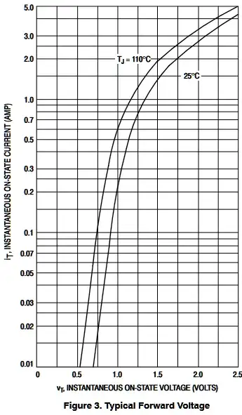
The incremental slope is the tangent over a small range for a log-lin plot of Ron=ΔVt/ΔIt. This example is from 3 Ohms to near 0.25 Ohm at the top.
\$\frac{P_D }{ P_{trig}}= \frac{V_T*I_T}{V_{GT}*I_{GT}}= \frac{1.2 ~W}{0.00016~W}=7500\$
This is the best-case power-gain computed but pulsing higher currents to guarantee faster gate turn-on from input capacitance is where one you expect to derate these ratios. But due to the diode drop, these are not as good a switch as Power Mosfets or even common-emitter Rce, but they are latching and that's the tradeoff.
All the other parameters are given for pulsing, derating, dynamic and thermal effects beyond 1A which raises Ron from secondary junction effects.
But it is useful to understand current triggering and voltage triggering are almost the same thing related by this threshold resistance to make linear out of exponentials.
Conclusion
What causes this holding current?
If you look back at the Rin/RLout = 40 resistance ratio to trigger the output and apply that to holding current, Ih=5mA, 5mA/40 = 125 uA you get a fraction of the 200 uA input trigger current but due a higher output voltage, this is resistance and current ratio is all that is necessary to keep the input self-biased from positive feedback. After all, transistors are Vbe-controlled current sinks that we can model with current gain and impedance effects.
This internal positive feedback is what makes them work as latches.