3

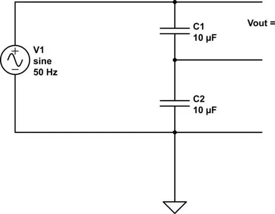
I saw the following voltage divider on YouTube:

Simple convert 220V to 110V

And I saw it is a so-called voltage divider using capacitors: Capacitive Voltage Divider as an AC Voltage Divider

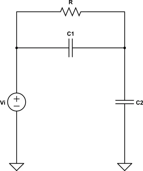
And I thought to implement the following circuit:

schematic

simulate this circuit – Schematic created using CircuitLab

Based upon the site, I find with a 10 µF capacitor and 220 V 50 Hz AC the voltage across C1 is 99 V and not 110 V.

Based on the site's formulas, the C1 + C2 "resistance" is about 637 Ω.

The reason why I need to do this is to make an el-cheapo heatgun on a leftover 120 V soldering iron that I cannot use because in Greece where I live the power is in 200 V AC and if I plug it in it may cause harm to myself and be fried as well.

So I want to ask:

  1. Is a good idea to use a voltage divider as power supply to soldering iron as heating element?
  2. Do I need smaller capacitors?
  3. Will electrolytic capacitors fit the job for my application?

The soldering iron is a 60 W one. The idea is to implement something like this:

How to Make Hot Air Gun from Soldering Iron

In order words, to place a cheap 12 V pump as air flow and pass it from a soldering iron tip.

Peter Mortensen
  • 1,679
  • 3
  • 17
  • 23
  • 1
    What is the power rating of the 120 V soldering iron? (It is unlikely to be high enough to make an effective heatgun.) – Andrew Morton Nov 17 '21 at 17:35
  • 8
    1: No 2: N/A 3: No What you need is a travel transformer. Fortunately, these are very cheap and easy to come by and they work very well for pure resistive loads. – vir Nov 17 '21 at 17:35
  • If you really want to hack your soldering iron heating element to work on 200+V you may have more luck with a dimmer circuit. I take no responsibility for any safety implications. This is just a circuit design idea. – user253751 Nov 17 '21 at 18:13
  • ”Greece where I live the power is in 200V AC” 220 V by any chance? – winny Nov 17 '21 at 18:58
  • 3
    Just since nobody has mentioned it: Attempting to use electrolytic capacitors for this is not just a bad idea that won't work, it could be very dangerous, as electrolytic capacitors are prone to exploding when in reverse polarity. – sondre99v Nov 18 '21 at 10:04
  • 1
    @winny - well, if you want to correct the OP, then: 230 V. There has been no 220 V anywhere in Europe for quite some time now. :-) – Gábor Nov 18 '21 at 14:20
  • @Gábor Indeed. Many 220 V circuits are still in use though. – winny Nov 18 '21 at 15:34
  • A diode would do a job if it's an ordinary non-thermostatic soldering iron. It half wave rectifies the AC, giving you effectively half the voltage (approx) and 1/4 the power. – Rich Nov 18 '21 at 22:40
  • Are you really, really fond of the soldering iron, or would you consider looking for a 230V version, perhaps on the equivalent of Craigslist? – Technophile Nov 23 '21 at 16:09
  • I have a 230V also because I needed to re-order it, and I'm stuck with the 100V in Greece where is practically useless. – Dimitrios Desyllas Nov 24 '21 at 09:49

4 Answers4

15

Why?

  1. Because the two capacitors are not identical due to tolerance.
  2. Because the top capacitor is loaded with something that you don't show in the schematic diagram, and the bottom one is not

Is a good idea

Absolutely not!. That circuit may be good enough to light an LED, certainly not for a load of any significant power, such as a heat gun.

The only time we use capacitor dividers is at radio frequencies (megaHerz, gigaHerz), and rarely at high power.

Do I need smaller capacitors?

No, you need to start from scratch and use a transformer instead.

Will electrolytic capacitors will fit the job for my application?

No. You're working with AC, and electrolytic capacitors are polarized (work at DC). *

(*) There are some non-polarized electrolytic capacitors but they are only good for low power audio applications.

Davide Andrea
  • 21,104
  • 6
  • 34
  • 73
10
  1. No, on the contrary, that is an extremely bad idea.

  2. No, you don't need capacitors at all.

  3. No, electrolytic capacitors would be an extremely bad idea too.

You really don't adapt a 60W 110V device to 220V mains with a capacitive voltage divider made of electrolytics. Use a transformer.

Electrolytic capacitors are typically polarized capacitors that cannot handle voltage in reverse, so that's why they are wrong type.

Also a 10uF capacitor has 318 ohms of impedance at 50 Hz. A capacitive divider with 10uF capacitors would thus have 159 ohms output impedance to load. So it would not work to power a 110V 60W load which requires about 0.55A of current, and can be assumed to be just a load of 200 ohms, so the capacitive divider with 159 ohms can't drive such a high load.

Justme
  • 147,557
  • 4
  • 113
  • 291
  • Bad idea why? No why? Low quality answer – Willy Wonka Nov 18 '21 at 08:17
  • @WillyWonka any better now? The point was just that capacitors are a wrong approach and a transformer should be used. This question is also basically not about electronic design, there's an X-Y problem, in the end this is about how to use a 110V device in 220V country. – Justme Nov 18 '21 at 08:42
  • Yes, much better – Willy Wonka Nov 18 '21 at 09:23
2

Well, when we have the following circuit:

schematic

simulate this circuit – Schematic created using CircuitLab

It is not hard to see that:

$$\underline{\text{V}}_{\space\text{out}}=\frac{\text{R}\text{||}\frac{1}{\text{j}\omega\text{C}_1}}{\frac{1}{\text{j}\omega\text{C}_2}+\left(\text{R}\text{||}\frac{1}{\text{j}\omega\text{C}_1}\right)}\cdot\underline{\text{V}}_{\space\text{in}}=\frac{\text{C}_2\text{R}\omega}{\text{R}\left(\text{C}_1+\text{C}_2\right)\omega-\text{j}}\cdot\underline{\text{V}}_{\space\text{in}}\tag1$$

So, the amplitude is given by:

$$\left|\underline{\text{V}}_{\space\text{out}}\right|=\frac{\text{C}_2\text{R}\omega}{\sqrt{1+\left(\text{R}\left(\text{C}_1+\text{C}_2\right)\omega\right)^2}}\cdot\left|\underline{\text{V}}_{\space\text{in}}\right|\tag2$$

In your example we know that \$\left|\underline{\text{V}}_{\space\text{in}}\right|=220\sqrt{2}\space\text{V}\$, \$\text{C}_1=\text{C}_2=10\cdot10^{-6}\space\text{F}\$, \$\text{R}=\frac{605}{3}\space\Omega\$ and \$\omega=100\pi\space\text{rad}\$. So the amplitude for the output voltage will be:

$$\left|\underline{\text{V}}_{\space\text{out}}\right|=\frac{10\cdot10^{-6}\cdot\frac{605}{3}\cdot100\pi}{\sqrt{1+\left(\frac{605}{3}\cdot\left(10\cdot10^{-6}+10\cdot10^{-6}\right)\cdot100\pi\right)^2}}\cdot220\sqrt{2}=$$ $$13310 \pi \sqrt{\frac{2}{90000+14641 \pi ^2}}\approx122.115\space\text{V}\tag3$$

Jan Eerland
  • 7,790
  • 12
  • 21
-1

For a small and thrashbin-sourced project, the capacitive divider is pretty much a viable option.

The caveat is to know what you are doing.

If your heat gun is only a heater element and does not contain a control logic or something else that can depend on voltage and fears of voltage spikes on power-on, you may as well go with a single capacitor.

The heating element is 240 Ohm (60W at 120V). The total resistance should be twice that (480 ohm). The capacitor has to be sqrt(3) * 240 Ohm at 50Hz, so it gets more or less 7.7uF.

The voltage over the cap will be ~300V peak and the reactive power will be like 105W (both are important when sizing the capacitor).

Be sure to parallel the capacitor with 100k .. 1M resistor in order not to get refreshing shocks from the power plug.

fraxinus
  • 9,184
  • 11
  • 35
  • I don't believe a capacitive divider is viable here, for reasons already mentioned in other posts. Please do not encourage a novice in taking this dangerous, ineffective approach. – Technophile Nov 23 '21 at 16:11