2

enter image description here

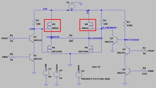
I searched the internet and made h-bridge circuit:

By combining resistor R5 and R7 are connected to, when I give the pin HIGH, it will rotate counterclockwise when I give it LOW in the clockwise direction. I also shared the PWM pins. I will use this pin for PWM or activating.

My MOSFETs are not in LTspice. I see a voltage drop in the MOSFETs in the circuit. I could not fix them.

Do you think this circuit will work?
  • 6
    If you simulated it and already found it not to work yourself, what is it that you are actually asking? – Justme Oct 23 '21 at 15:47
  • 3
    What's it for? You've tagged it "electronic load" but then you mention changing directions - but there's no motor in the circuit. – JRE Oct 23 '21 at 15:47
  • 3
    Potential problem with shoot-through current on those MOSfets while they switch. – glen_geek Oct 23 '21 at 16:05
  • 2
    Add specifications to your question. "Working" could mean different things to different people. A circuit used to stress test transistors until they fail might "work" in the sense of doing what is intended, even if they t doesn't work in the sense of reliably controlling some load. – Math Keeps Me Busy Oct 23 '21 at 16:51
  • Side note: using the generic PMOS will not give you what you expect. Select on from the database, even if it's not exactly one that you want. – a concerned citizen Oct 24 '21 at 16:33

1 Answers1

11

Do you think this circuit will work?

No, your H-bridge circuit won't work: -

enter image description here

Your PMOS devices are upside down. This means that the bulk diode inside them will cause an unholy amount of current to flow when either of the NMOS devices are activated.

Plus, when you fix that problem you'll get shoot-through issues due to the sloppy way you are driving the gates.

Andy aka
  • 456,226
  • 28
  • 367
  • 807
  • Thanks a lot.What exactly does it mean sloppy. – bahadır güven Oct 23 '21 at 17:32
  • 2
    It means that as you allow M1 to become activated by switching off Q1 and Q3, the gate voltage rises quite slowly (due to gate capacitance) and, for a small period of time, both M1 and M3 are activated simultaneously and you get a massive surge of current through them. That's called shoot-through. Your circuit is very naïve but, is a commonly proposed naïve circuit by many beginning this subject. There are literally dozens of examples on this site of people making this kind of naïve mistake so, you are in good company (or bad depending on your opinion). – Andy aka Oct 23 '21 at 17:45
  • @bahadırgüven are we done here? If so then you should take the two minute tour to understand why people give free help on this site else, raise another comment should there be something you want to ask. – Andy aka Oct 24 '21 at 14:45
  • thank you i have no more questions. – bahadır güven Oct 24 '21 at 16:07
  • @bahadırgüven then you need to mark this answer as accepted (as per site guidelines that I drew to your attention in my earlier comment). – Andy aka Oct 24 '21 at 17:09
  • sorry i didn't know .I accepted your answer. – bahadır güven Oct 28 '21 at 21:05