1

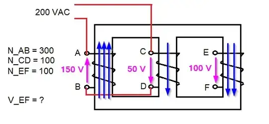
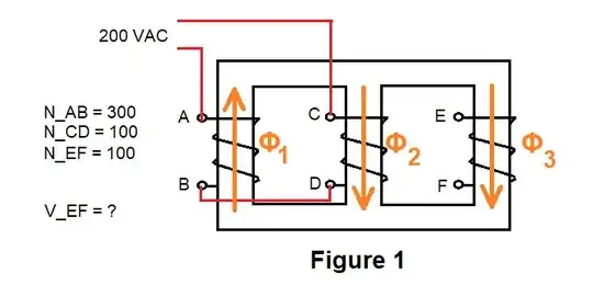
Given the circuit in Figure 1, how would one go about finding V_EF?

Figure 1: Magnetic circuit

For me it is clear that V_AB + V_DC = 200 and that the current through windings AB and CD is the same.

In addition, Φ_1 = Φ_2 + Φ_3.

The approximation of the sum of magnetomotive force around a closed loop beeing equal to cero does not hold here. Why is it the case?

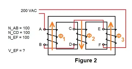
And how would the case in Figure 1 compare with the one shown in Figure 2? Where Φ_1 + Φ_3 = Φ_2 and flux cannot be distributed in a per-turn basis. Figure 2: Magnetic circuit
I would appreciate pointers to relevant material on the subject. I have not been able to find examples of magnetic circuits with several coils as depicted. I'm not as interested in the specific case as in the more general principles at play.

Thanks.
JSF
  • 11
  • 3
  • 2
    "In addition, fluth through AB plus flux through CD must equal flux through EF." Wouldn't they be equal to flux through FE? Draw in the flux lines for AB and CD and then add in the flux lines for EF. Maybe draw one flux line for every 100 turns. Add the sketch into your question. – Transistor Sep 30 '21 at 18:39

2 Answers2

3

I haven't had to work with magnetic circuits much but my intuition would be to represent the flux in the core as shown below. The AB branch would have three times that of the CD branch due to the windings ratio.

enter image description here

Figure 1. Since the sum of the fluxes in all branches must equal zero there must be "two fluxes" in the EF branch and in the relative direction shown.

Since "one flux is worth 50 V" then VEF = -100 V (where '-' represents 180° relative phase).

Transistor
  • 175,532
  • 13
  • 190
  • 404
  • Thanks. I understand the reasoning, yet I don't know when to apply it. For example, I've added another circuit Figure 2, in which flux is no longer related to turns ratio. – JSF Oct 01 '21 at 17:28
0

Based on the diagram alone, since AB & CD are receiving power out of phase, one would expect the core to go into full saturation and to find zero usable voltage. If we measure EF open-circuit pre-saturation, we should see 100V, since T1 = 300n-100n = 200n, which puts our ratio at 2:1.

To give a better understanding of principle, how about we use the water analogy? If you had one water-slide split into two, with one having 75% and the other 25% flow. If you curved them to oppose one another and meet, you'd have massive eddy currents and a total flow at output of 1/2 the input flow-rate.

Magnetic Flux is distributed from the work coil on a per-turn basis, and we see 400 turns in the primary winding. 100 of those turns are counteracting 100 turns on the other side. Causing the effective Flux seen at the secondary winding to be (in a perfect world) 50% the input power. Considering eddy currents and core saturation, losses are far greater in most real-world systems set up like this. Before transistors were cool, heavy military radios used the concept of core saturation (and DC voltage bias) to cause cores to amplify signals when brought out of saturation. If you're interested, they are known as 'mag amps' and are fun to study and build.

  • Thanks. What do you mean by T1? – JSF Sep 30 '21 at 19:22
  • T1 in this case represents Transformer winding one (both powered coils); sorry, poor notation. – Christopher Karr Sep 30 '21 at 20:17
  • Thanks. And very interesting reading on mag-amps. The explanation makes sense yet I'd like to know when or how is flux distributed on a per-turn basis. See Figure 2 above. – JSF Oct 01 '21 at 17:33
  • I'm confused. Your second diagram is describing a six-pole electromagnet with huge losses. My best way of teaching about transformers is with laminated-core style. The core itself is a collection of short-circuited windings which are then turned into one 'winding' of the core. If your core has 10 laminations and you feed 100V@1A to the primary, each lamination will be a carrier of 10W. That energy is then transferred to the other coils within the core. When the core hasn't the power-handling to accommodate more Flux, it reaches saturation. That is the core itself being a charged inductor. – Christopher Karr Oct 01 '21 at 18:37
  • Sorry if I wasn't clear. These circuits do not necesarily have to be transformers. What I don't understand is why in Figure 1 flux is distributed on a per-turn basis and in Figure 2 it does not. Not just why, but how would I sistematically solve these circuits. – JSF Oct 02 '21 at 16:38