2

I am a semi-retired Electrical Enginerr, and this question has me perplexed.

I don't need any info on capacitors, series calculations, transition effects, etc...

Here is the complete question but I'm just rusty on the charge distribution at equilibrium (and the energy) despite having read quite a few articles. That's what I'm mostly interested in help with. enter image description here

enter image description here

3 Answers3

2

The original charge in \$C_1\$ (when attached to the voltage) is now shared with the two previously discharged capacitors. In other words \$C_1\cdot V_0\$ becomes equal to \$C_{NEW}\cdot V_{NEW}\$.

  • \$C_{NEW}\$ is the combined capacitance as seen from the top node to the bottom node.
  • \$V_{NEW}\$ is new voltage as seen from the top node to the bottom node.

There is of course the mystical loss of energy due to infinite current flow for an infinitesimal period of time whan the discharged capacitors are attached but, the number of electrons that form the charge remain the same number as when C1 was originally charged (i.e. none of that energy mass conversion stuff).

I'll also point out that the charge into the two new capacitors is the same (because they are in series) hence the voltages across each of them can be found using the basic Q = CV formula.

\$V_{C_2} + V_{C_3} = V_{NEW}\$ is also true.

As for whether all the capacitors are in series is down to how you look at the voltages. You can say they are all in series if you want. I prefer to think that C2 and C3 are in series then, together they become in parallel with C1. I think you should think that way in order to calculate V2.

Of course you can think of them in series because the charge that is redistributed (when C2 and C3 are added) flows equally through them all.

Andy aka
  • 456,226
  • 28
  • 367
  • 807
  • Thanks for your reply.OK, let me clarify my understanding. Original Q1 = C.Vo. But when connected to two new caps, I thought that Q1 = 1/2 CVo; and Q2 = Q3 = 1/4 C.Vo...which all add up to original charge = C.Vo. But my reading about series cap suggests that all 3 caps will have the same amount of charge...and if so, how much charge do they each have ? 1/3 of original charge ? This is the bit Im perplexed about. – lowtech1962 Sep 25 '21 at 12:14
  • Calculate the new net value of capacitance (top node to bottom node) and work out the new value of voltage. The charge is conserved and, it seems, you know how to work out the new capacitance value hence, you'll find the new value of voltage from top node to bottom node. – Andy aka Sep 25 '21 at 12:25
  • Thanks again. Getting VERY close to my issue. Vnew=Vo/2 = Vc2 + Vc3. So , Vc2 = Vc3 = Vo/4. So, knowing the voltages across each cap, I calc the charge in each cap, so that Q2 = Q3 = 2C.Vo/4 = C.Vo/2....... and Q1 = C.Vo/2......BUT now we have C.Vo/2 in each of the 3 caps...which adds up to 3/2.C.Vo !!!! This is where I am perplexed. What am I doing wrong...the voltages are correct...but charge is ? – lowtech1962 Sep 25 '21 at 12:39
  • Yes, Vnew = Vo/2 hence Vc2 = Vc3 = Vo/4. The charge in C2 is simply $C_2.Vo/4$ and not 2C.Vo/4 – Andy aka Sep 25 '21 at 17:52
  • Thanks again for your time. The value of C2 and C3 are 2C farad. So shouldnt the charge in each (of C2 and C3) be 2C.Vo/4, which reduces to C.Vo/2...which is double what u suggest (i think?) and is the source of my confusion. How do we have C.Vo/2 charge in each and all 3 caps ? I clearly have a blind spot in my understanding at this point. – lowtech1962 Sep 26 '21 at 05:14
  • It's the same because the charge that redistributes in all three is the same because you can regard them as being in series. – Andy aka Sep 26 '21 at 09:36
  • Yes, but its more than the original charge. Doesnt total charge have to stay constant ? – lowtech1962 Sep 26 '21 at 09:38
  • It can't be more than the original charge so something somewhere has gone wrong in your calculation. – Andy aka Sep 26 '21 at 09:50
  • Agreed. Something is wrong. When C2 & C3 treated as one cap = C farad..no problem. But when they are split into 2 x 2C farad, the increase in capacitance gives impression/calculation of increased charge (beyond original) ...but I dont see why ? Maybe voltage division is only valid for AC, not DC conditions ? – lowtech1962 Sep 26 '21 at 12:24
  • The charge in series capacitors is not additive - the same electrons are used in both therefore you can't just double the number of electrons because two capacitors are in series. Read this i.e. $$Q_{TOTAL} = Q_{C1} = Q_{C2)$$. – Andy aka Sep 26 '21 at 12:35
  • Mathjax doesn't appear to be working in the formula above so I've written it here Qtotal = Q(C1) = Q(C2) etc... – Andy aka Sep 26 '21 at 12:40
  • OK, thanks. The link and your edit answered the question I had about the series capacitors, and the ''odd'' (imo) fact that the total charge for several series caps is equal to the charge on each cap in that series. I will now focus on understanding that interesting property. Thanks for your time ! – lowtech1962 Sep 26 '21 at 14:31
  • @lowtech1962 maybe think about it in terms of current through series elements; you wouldn't say that the total current through 2 series elements is double the common current and, remember that current is just rate of flow of charge. – Andy aka Sep 26 '21 at 15:06
0

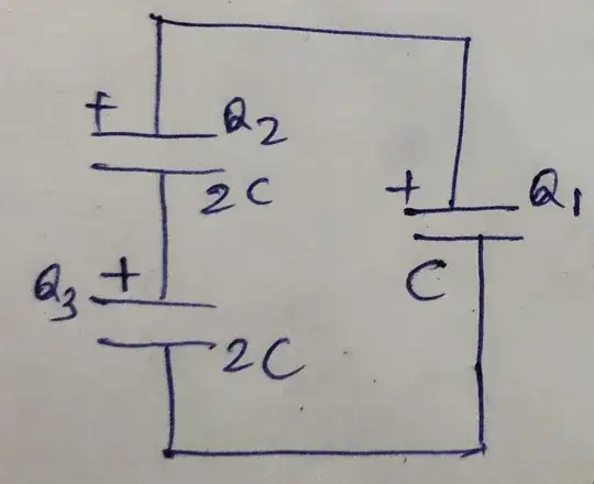
When the voltage source is replaced by 2 series caps the voltage across C1 will halve and so from Q=CV its charge will also halve.

The two other series caps in parallel to C1 will each have half the voltage across them, (half the voltage which is now across C1), but each of their capacitances is double that of C1. Therefore, from Q=CV, each of their charges is equal to that of C1's final charge.

So, as you suspected all three capacitors have equal charges but each is equal to half the original charge of C1.

I think you're having difficulty sorting this one out because your wrongly thinking that the total final sum of the charges of all three capacitors should be equal to C1's original charge but the redistribution of charge is caused by the flow of series current in the 3 capacitors and so the same current flows "through" the two series capacitors (which are in parallel to C1) carrying the charge to both of them.

EDIT

At the instant when the voltage source is replaced by two series capacitors a current starts to flow in an anti-clockwise direction around the circuit (talking about positive charge flow ie. conventional current). No conduction charge actually flows between the capacitor plates (apart from a tiny leakage current) but flows onto the uppermost plate of each of the two series capacitors and off of the lowermost plate of each of the two series capacitors. With regard to C1, the positive charge is flowing off (being removed from) its uppermost plate and flowing onto its lowermost plate. So the series current (flow of charge) is the same magnitude and direction at all points in the circuit.

This means that the series current is removing charge from C1 at exactly the same rate as it is adding charge to both C2 and C3.

Looking it another way, the rate of positive charge flow off the top of C1 and onto the top of C2 is the same as the rate of positive charge flow off of the bottom of C3 and on to the bottom of C1. Additionally the rate of charge flow off of the bottom of C2 and onto the top of C3 is the same.

And so the C1 discharge current is the same as the charge currents of both C2 and C3.

It may, at first seem a little difficult to understand how charge can flow off of the bottom of C2 and on to the top of C3 when the voltage at those point is identical but whilst this is happening, in collaboration with positive charge flowing onto the top plate of C2 and off of the bottom plate of C3, the voltage across both capacitors is increasing.

When considering capacitor charging it is good to remember that the currents in the leads of the capacitor always have the same magnitude but one flows in and one flows out. Then both currents change direction when discharging.

  • Yes..."total final sum of the charges of all three capacitors should be equal to C1's original charge" ...is what I expect...and from the voltages across each cap, I get a total of 3/2.C.Vo...which is 50% more than original charge = C.Vo. Where does the extra charge come from ? Sorry, Im still not seeing it. – lowtech1962 Sep 25 '21 at 13:59
  • Can u elaborate on how the charge appears to increase, due to the current flow thru all 3 caps ? I feel that this is the missing link in my understanding... it seems to contradict conserv of charge ? but i sense series caps distribute charge in a way I dont get. – lowtech1962 Sep 25 '21 at 15:17
  • Thank you again for your detailed reply., which I have tried to include in my new diagram (added above) .... but I still see a discrepancy about total charge, after connection. If u have time to address that, it would be appreciated. – lowtech1962 Sep 26 '21 at 05:23
  • To all: I have figured out that this is an adapted version of the ''two capacitor paradox'', but with two series caps in the connected branch...which is the bit I'm having trouble with. – lowtech1962 Sep 26 '21 at 05:32
  • Thanks for your replies above. I need to study this series charge property a bit more to fully appreciate it. – lowtech1962 Sep 26 '21 at 14:34
0

Let's consider the following charge configuration (in image)

enter image description here

from Charge conservation $$Q_1 + Q_2 =V_o C$$

$$-Q_1-Q_3=-V_o C$$

Using KVL

$$ -Q_1/C + Q_2/2C + Q_3/2C =0$$

again charge conservation

$$-Q_2 + Q_3 = 0 $$

Solving these three equations we get

$$Q_1 = Q_2 = Q_3 = V_o C/2$$

user215805
  • 1,174
  • 1
  • 7
  • 20
  • Thank you for your reply. (1) Q1+Q2+Q3=Vo.C (agreed). .....(2) KVL (agreed)..... (3):Q2=Q3 (agreed)..... (4) this is consistent with the principles of series capacitance........but now I have 3 caps in series, with equal voltages across them, and equal charges...and I dont think your diagram is still valid...as two LHS voltages are opposing the one RHS voltage. Sorry I am still perplexed. – lowtech1962 Sep 25 '21 at 14:17
  • @lowtech1962 equal charges on them - yes , equal voltage across them -No because V1 = Q/C, V2=V3= Q/2C and series configuration doesn't imply equal terminal voltage, terminal voltage are equal in parallel not in series – user215805 Sep 25 '21 at 14:27
  • OK, understood. Equal charges on each of Vo.C/3.....which gives voltages: V1=Vo/3; V2 = V3 = Vo/6 ....... Now Im wondering, why has original Vo dropped to Vo/3 and not Vo/2 ? This contradicts other results I have seen....? – lowtech1962 Sep 25 '21 at 15:10
  • @lowtech1962 1. Why should Vo has to dropped Vo/2 ? And if we still try to make it Vo/2 , we end up violating charge conservation or KVL 2. There is one and only one configuration is possible (from uniqueness theorem) which didn't violate charge conservation and KVL.3. Can you precisely tell which results you have seen that contradicts my solution? – user215805 Sep 25 '21 at 15:40
  • I should clarify. By Vo I mean the voltage before connection across C1. So after connection I believe the voltage across C1 reduces to Vo/2. This result is mentioned in the other posts, and in discussions about the ''two capacitor paradox''. However , this circuit is a little different from those...hence my confusion. I have since read that this question deviates from normal circuit theory rules (Wikipedia: Two capacitor paradox). Thanks for your input. – lowtech1962 Sep 26 '21 at 05:38
  • @lowtech1962 ah i see, from your edit i got your point, so basically we got two different answers using two methods (one that i used and 2nd is your) and only one is correct (and it should be mine because it didn't contradict any fundamental principles while your solution violate charge conservation) , so the question is where did you go wrong in your solution because it also apparently seems like you also followed basic principles , although I'm not sure but one thing that bothered me in your solution is the assumption of series combination of C2 and C3 during transient. – user215805 Sep 26 '21 at 11:31
  • Because in case of two capacitor paradox (given in wiki) , there are 3- 4 four possible model which tells us about lost energy, and if we pick the simplest model (i.e resistor and capacitor model) we can show that half of the energy lost in the resistor but the problem in 3 capacitor case is that we can place resistors (for example if we place a resistor parllel to capacitor)such that they series combination of C2 and C3 wouldn't valid and hence your assumption of series combination fails, but I'm not 100% sure, feel free to add something – user215805 Sep 26 '21 at 11:39
  • Something is wrong. When C2 & C3 treated as one cap = C farad..no problem. But when they are split into 2 x 2C farad, the increase in capacitance gives impression/calculation of increased charge (beyond original) ...but I dont see why ? Maybe voltage division is only valid for AC, not DC conditions ? – lowtech1962 Sep 26 '21 at 12:26
  • @lowtech1962 , I think my mistake was to use charge conservation wrongly, I'll edit it. – user215805 Sep 27 '21 at 13:48