simulate this circuit – Schematic created using CircuitLab
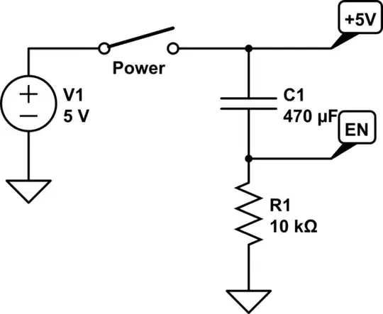
I am trying to generate a single high pulse (+5V) in the node EN when power is switched on, and then I want EN to give a low signal (0V) for the rest of the time that power is on.
I found this answer which suggested this circuit. How does the capacitor C1 discharge when the power is switched off? This circuit doesn't seem to allow to current to flow in the opposite direction.
