Below is exactly how the circuit should look. R1 should be chosen to get the desired LED current. D1 can be a single LED, or multiple LEDs in series (not in parallel!).
R2 is a pull-down resistor on M1's gate so that when the Arduino is initializing, the LED will remain OFF until the output pin is driven high for the first time. R2's value is not critical, anything in the range between 10kΩ and 1MΩ will work.
It is important that the 12V supply is attached directly to the source of M1 and to the top of R1. The source of M1 is then a star grounding point where the 12V supply's negative side connects with the digital ground of the circuit.
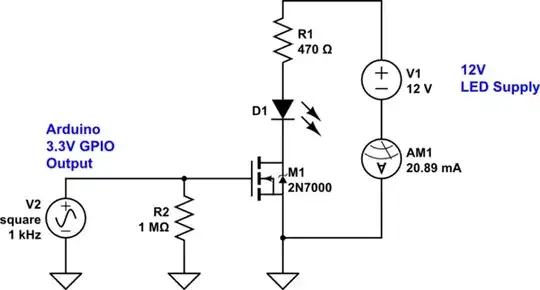
simulate this circuit – Schematic created using CircuitLab
The LED turns on when the GPIO is at high logic level. E.g. digitalWrite(ledPin, HIGH) will turn the LED on, and digitalWrite(ledPin, LOW) will turn it OFF.
I think I was expecting the 2N7000 to act opposite.
The pin state is determined by your code, so which way the MOSFET acts is of no concern. You can easily adapt the software to provide the logic level needed to turn the LED on and off no matter which way M1 acts. As shown, a HIGH level turns the LED on. If you want a LOW level to turn the LED on, just write a function that inverts the signal:
constexpr const int8_t ledPin = ...;
inline void setLedState(int8_t state)
{
  if (state==HIGH) digitalWrite(ledPin, LOW); else digitalWrite(ledPin, HIGH);
}
Addressing some of the comments:
The link to the solution diagram is no longer valid (dl.dropbox.com/u/11643892/2N7000-2.png)
That's why it's a bad idea to use anything other than the image hosting built into this site (at the moment it's StackExchange's imgur account).
This is the most logical and intelligent answer I have seen how this particular 2N7000 mosfet works.
All N-mosfets work the same really. So nothing you read here has much to do with the particular 2N7000 mosfet.
The only N-MOS specs matter here are the threshold voltage and channel current capacity. If the threshold voltage is higher than about 2V, then the 3.3V logic output of an Arduino won't be high enough to fully turn the N-MOS on. In that case, you'd need to use a little voltage multiplier to step up the voltage from the Arudino - shown below.
The channel current capacity (maximum drain current) determines the maximum LED current allowed before the N-MOS will begin to sustain damage.
It is often the case that we may have an N-MOS device that has too high a threshold voltage to be controlled by logic levels directly. This is common with mosfets recovered from e-waste power supplies.
To cope with that, we need two things:
A gate drive voltage generator that will supply 10-15V. The current needed is fairly low, so this doesn't need to be anything fancy.
A level translator that will take the 3.3V logic level output and translate it to the 10-15V voltage from the generator above.
To get a 10-15V supply, we take a square wave output from an Arudino and pass it through a voltage multiplier:
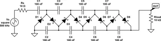
simulate this circuit
Schottky diodes an be almost any type rated for 100mA average forward current. The 10kΩ load is just for illustration, an actual gate load will be much higher impedance as low as the PWM frequency (if any) is kept low, say 1kHz or so.
To translate the Arduino 3.3V GPIO output to this higher level, use CD4504 or CD40109 for example.
CD4504: pin 8 is GND, pin 1 - 3.3V, pin 16 - output of the voltage multiplier, pin 13 connect to pin 16, pins 3,5,7,9,11,14 are inputs and pins 2,4,6,10,12,15 are their respective outputs; the logic function is an inverter.
CD40109: pin 8 is GND, pin 1 - 3.3V, pin 16 - output of the voltage multiplier, pins 2,7,9,15 connect to pin 1, pins 3,6,10,14 are inputs and pins 4,5,11,13 are their respective outputs; the logic function is a logic buffer.