I am making a device that provides a maximum of 35 mA @12V DC for a skin care system through a wire. I have a 12 V DC supply capable of 120 watts. What is the safest and simplest way to limit the current through what is essentially a short across the 12 volt supply
-
3Safest and simplest are not usually good friends. Especially when talking about personal care systems. And you are talking about a product which has a compliance current that is quite high. Why? (I read the 35 mA but then I read the 120 W. I'm confused about that.) Does skin care require anything like that, ever? Or is there a heating element involved? I suppose you need to provide more detail. But if all you need is 35 mA, then there are easy circuits that will limit that. WIthout much more, you can have a foldback circuit, which may be better. But who knows? – jonk Aug 09 '21 at 07:42
-
112 V 35 mA is not consistent with 'essentially a short across the 12 V supply'. Which is it it? We need details of the load to provide any guidance. – Neil_UK Aug 09 '21 at 10:05
-
If you are applying 35mA to a person, this might violate medical requirements and safety standards. Also in the event of a fault you could kill someone. You might want to check your local laws and regulations – Voltage Spike Aug 16 '21 at 18:54
2 Answers
That 120W rather suggests the PSU can source 10 Amps. If you only want 35mA out of that and want a cutout for higher (fault) current the simplest method is a fuse. They are available from 20mA upwards. You would also have to take into account switch-on, switch-off current pulses. You can also get resettable fuses down to about 100mA
- 13,723
- 9
- 54
- 115
-
4Note however a 20mA fuse will take a long time to blow at 35mA and probably require about 100mA to blow in less than a second. Whether this is adequate protection is above my pay grade here... – Aug 09 '21 at 12:13
If your load is like a short or is otherwise very low resistance, then you can't output 35mA at 12VDC through it. This is hard physical impossibility that cannot be worked around.
Look at what ohm's law tells you here:
\$ V=IR\$
I don't know how long or what gauge or material the wire you're using as a load is, so it is hard to say what the resistance of it is. But let's just make up a number, and call it 50mΩ. The only way you will ever get 35mA to flow through that 50mΩ wire is by putting \$ 0.035A*0.05Ω = 0.00175V \$ across that wire. If you put 12V across it, no matter what, you'll cause 240A to flow through that wire. Fortunately, this will make the wire become dual purpose, as it will act as its own fuse.
I mention this because you need to be sure what it is you actually want. Because unless your load has a much higher resistance of about 342Ω, you cannot have 35mA flowing through it while also having 12V across it. And while there are many methods of limiting current, all of them have the same mechanism: they will reduce the voltage across the load to however low it needs to be to limit the current to what you want.
So all methods you can use to limit the current to 35mA will do so by reducing the voltage across that wire to whatever it needs to be for 35mA to flow, according to that load's resistance and Ohm's law.
If you want 35mA and want 12V across the wire, the only way you can achieve this is with a wire that has 342Ω of resistance.
If you actually just want 35mA and don't care what the voltage across the wire is and are ok with whatever voltage is needed to limit the current to that level (though I doubt this is what you are after either, as for, say, a 50mΩ wire, this is an absolutely minute amount of power and I can't imagine it would do anything to anyone's skin), the easiest way to do that would simply be a constant current regulator.
These regulators work by dropping enough voltage across them (they sit in series with the load) such that the total current draw through the regulator and the load is the desired current set point.
For small currents like 35mA, these are typically called current sources or constant current sources.
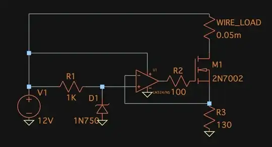
The simplest but still robust method is, in my opinion, simply using an op amp to control a MOSFET. A zener diode provides a voltage reference, and the op amp will actuate the gate of the MOSFET so the voltage drop across a sense resistor stays equal to that reference voltage. What results is a circuit that will always sink \$ \frac{V_{sense}}{R_{sense}} \$ of current through a load. I chose a 4.7V Zener and a 130Ω sense resistor:
Do note that the MOSFET will dissipate roughly 250mW at 12V input, so it will get pretty warm depending on the package, but 250mW of heat is easily sunk into even a small pcb then passively cooled with the added surface area.
- 28,520
- 4
- 68
- 120
-
1It won't do anything to the skin, but the patient (victim) [sucker] will detect it. – StainlessSteelRat Aug 09 '21 at 15:44
