3

I know that this is a very basic question. While learning electronics, I see the phrase "the impedance looking into X" very often (e.g. in The Art of Electronics, 3rd edition), but I haven't seen a clear definition. As someone with good background in physics, I can easily understand the meaning of "the electric potential at point Y" or "the current in some wire", but a similar phrase involving impedance is something completely new to me.

For example, in the following circuit, what is the impedance looking into Point A?

schematic

simulate this circuit – Schematic created using CircuitLab

apadana
  • 1,032
  • 1
  • 11
  • 23
  • 2
    It means what would be the impedance seen between the point A and the ground (Thevenin resistance in your case). – Eugene Sh. Jun 24 '21 at 13:27
  • 1
    Usually with respect to ground if nothing else is stated. If you have a differential input, you normally refer to the impedance into the + port with respect to - port. – winny Jun 24 '21 at 13:29
  • @EugeneSh., here we have R2 between point A and the ground. Is that the impedance looking into point A? As far as I can remember according to books the impedance is R1 || R2 here. – apadana Jun 24 '21 at 14:24
  • 1
    Don't forget about the power supply which should be shorted according to Thevenin theorem. – Eugene Sh. Jun 24 '21 at 14:25
  • @EugeneSh., Thanks for your comments. But I'm looking for a clear definition, not recipes. I know what Thevenin resistance is, but unless I have a clear definition of "the impedance looking into X", I can't relate these. – apadana Jun 24 '21 at 14:29
  • 1
    The clear definition is given in the first comments. It is the impedance between the given points. If only one point is given, the second one is defaulting to the ground. That is which impedance would a device X "see" if connected between point A and ground. – Eugene Sh. Jun 24 '21 at 14:32
  • @EugeneSh., OK. Now I see, though I still have some problem understanding the meaning of the impedance of some circuit when (ideal) power supplies are included. Thanks anyway. – apadana Jun 24 '21 at 14:42
  • 1
    @apadana This is why I referred to Thevenin theorem. This will help with understanding what is equivalent resistance/impedance of a circuit with power sources. – Eugene Sh. Jun 24 '21 at 14:44
  • @EugeneSh., The Thevenin theorem may be helpful. It can make life easier but it's not necessary here. With a good definition of "impedance seen between two points" and Kirchhoff's Laws this problem must be solvable. Even Kirchhoff's Laws are nothing but simplified version of more fundamental laws, i.e. Maxwell's Equations, which are more difficult to work with. – apadana Jun 24 '21 at 17:45
  • @EugeneSh., And I'm actually looking for a quantitative definition of "impedance seen between two points". – apadana Jun 24 '21 at 17:48

4 Answers4

3

Impedance is defined as Z=U/I, so to define it you need two nets through which you define a current flowing and across which you define a voltage. "Looking into" is kind of a shorthand to talk about one net with respect to an implicitely defined local reference, with the added flexibility that the current out of the reference does not have to match the current into it:

enter image description here Imagine you look at the current going into your desired net. You would call that looking into that net.

For example, the impedance looking into the base of a transistor is the impedance between the base and the emitter in a common emitter configuration (and yet the current into the base is much different from what flows out of the emitter). For a differential signal, it would be relative to the - terminal.

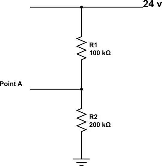
In your example, the impedance "looking into point A" is the impedance between A and GND, or 66.7kOhm following the base definition for impedance (open circuit voltage A-GND divided by short-circuit A-GND), but you can also consider that impedance is measured when all voltage sources are turned off - in this case 24V net shorted to GND => Z=R1//R2. Other tricks include looking for symmetry lines to find equipotential nets and short them to further simplify the circuit.

All of the above applies to steady-state/DC in linear circuits (i.e. only passives). You can do the same with dynamic signals and/or non-linear circuits by considering Z=dV/dI instead, as instantaneous/small-signal impedance around a DC bias point. It's basically like zooming in on the impedance plot (I=f(V)) that you would get "looking into" the net you want, until it's a line that's straight enough for your application: the system becomes by definition linear for small signals, and so you can solve the circuit one source ON at a time then sum the results.

Mister Mystère
  • 9,846
  • 6
  • 55
  • 83
2

Let's try this. Rather than thinking of the circuit as having an output at A, consider this circuit

schematic

simulate this circuit – Schematic created using CircuitLab

and ask, "What will the AC at point A look like?"

You'll find that R1/R2/24V will behave like

schematic

simulate this circuit

So, as far as V1 is concerned, when "looking into" the network, the network behaves like a 66.7 K resistor connected to a 16 volt supply. For AC purposes, the value of the supply doesn't matter, since it is fixed, and might as well be at zero for the purposes of AC analysis. So the impedance is 66.7 K.

WhatRoughBeast
  • 60,521
  • 2
  • 37
  • 97
1

You short the voltage source and find the resistance betwen the point and the ground. So you get $${200||100=66.7 k \Omega}$$

Tahmid Hassan
  • 356
  • 3
  • 10
1

The "impedance observed at point P in a circuit" refers to the derivative of voltage with respect to current when considering a current source between GND and point P. You will see it referred as "small signal input impedance" in some sources.

The fact we are calculating impedance as \$ dV/dI\$ instead of \$ V/I \$ allows us to disregard the 24V source.

FrancoVS
  • 1,563
  • 15
  • 29