I came across some custom Snap Circuits projects. One of them was a homemade SCR out of non polarized capacitors, two bipolar (NPN) and (PNP) transistors, some resistors, and an L.E.D. I am very familiar with how an SCR works and what it does. I am just wondering how this circuit works and why the L.E.D. stays on when I press the push switch. I have tried using a circuit simulator that I paid ten dollars for as well as visualizing the circuit. Nothing seems to be working. Thank you very much.
Asked
Active
Viewed 254 times
0
Transistor
- 175,532
- 13
- 190
- 404
james
- 11
- 1
-
1please use the schematic editor to draw the schematic diagram of the circuit – jsotola Jun 22 '21 at 22:49
-
Rather poorly, I imagine. – Hearth Jun 23 '21 at 00:02
1 Answers
6
Redrawing your snap circuit diagram as a proper schematic:
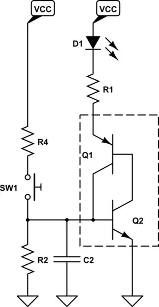
simulate this circuit – Schematic created using CircuitLab
Observe the dotted box - it contains the two transistors configured in a positive feedback arrangement. Individually, each of them is in a common-emitter-like configuration: When Q2's base rises about 0.7 V above its emitter (i.e. above ground) then Q2 begins to sink a current into its collector. Likewise, when Q1's base falls at least 0.7 V below its emitter, Q1 begins to source current out of its collector; the difference is that Q1 emitter is connected to a load of D1/R3 rather than directly to the voltage rail.
In the initial condition, the base of Q2 (i.e. emitter of Q1) is pulled down by R2; Q2 does not conduct, thus Q1 doesn't have base current and it doesn't conduct either. As soon as SW1 is closed, the voltage at Q2 base is pulled up by the combination of R4 and R2 -- if it's enough to make Q2 conduct, then it will do so, providing base current to Q1. Q1 turns on, and starts sourcing current into Q2's base; some of that current flows via R2 but enough of it flows into Q2 base to keep Q2 on. At this point, the switch can be released.
This keeps the circuit latched in an on-state, until some external mechanism (e.g. an increased load resistance, or loss of VCC supply) commutates the current until Q1 and Q2 can no longer stay on. Another mechanism for turn-off would be the Q1 collector current being shunted away from the base of Q2, e.g. if R2 briefly became a short circuit.
Of course, this is not as good as a dedicated SCR designed and manufactured for the task; there's a strong dependence on R2, R4, and transistor beta parameters for thresholds and proper performance.
A side note: You don't need a paid circuit simulator. Falstad and LTSpice are free and are good enough for circuits like these. By the time you really need a paid simulator, you're probably working in a lab or company where you'll already have licenses, and the software will cost thousands of dollars, not $10.
nanofarad
- 19,972
- 2
- 51
- 77