0

I want to switch a capacitive load with a PMOS once while running, then the continous current is maximum 13mA. The capcitive load is 2x10uF X5R, 1x1uF X5R and 1x100nF X5R, so pretty low series resistance and so I expect a pretty high current. Since the continous load is so low, I don't want to pick a huge FET if possible and I think by switching slower, the maximum current will anyway be way lower.

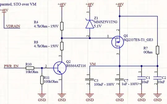
Here is the schematics: (The 0ohm resistor is only in case I want to bridge it) enter image description here
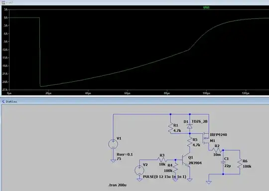
Further I made an LTSpice simulation, this shows a pretty large current of 26A, but I could not pick the same MOSFET anyway:

enter image description here

Do you think this is possible to achieve with a smaller FET or should I pick one with around 60A peak?
HansPeterLoft
  • 1,038
  • 1
  • 22
  • 40
  • 1
    The current in your simulation is so large because you have a very low ESR (Equivalent Series Resistance) of only 10 mohm. I would consider that unrealistic. I would find the datasheets of all the capacitors you're connecting, find the ESR of each capacitor and add that in series with each capacitor in the circuit. So I would replace that single 22 uF capacitor by models of the caps you're actually going to use. Then simulate what the inrush current is. – Bimpelrekkie Jun 16 '21 at 07:55
  • Also, can your supply deliver 26 A? Is there really no resistance in all wires? My guess is that a 2 A MOSFET will suffice, many MOSFETs allow for a short current peak that is significantly larger than their continuous current. Also think about how quickly the capacitors need to be charged. If some time is allowed, maybe a series resistor can be added so that the inrush current is limited. – Bimpelrekkie Jun 16 '21 at 07:57

1 Answers1

1

Switching the FET quickly will result in large current to charge the caps, and depending on how much capacitance there is on the 48V rail it might also cause the voltage to dip.

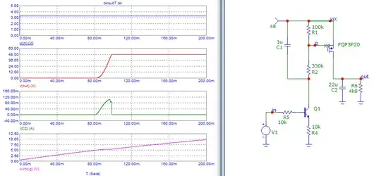
You can simply slow down the FET turn-on by adding a capacitor between gate and source, and increasing the values of R4 and R8.

Here Q1 acts as a current source to slowly charge C1, and R1/R2 divide that voltage to make a slow rising Vgs to turn on the FET very slowly. Inrush current is tiny.

enter image description here

bobflux
  • 77,207
  • 3
  • 91
  • 222