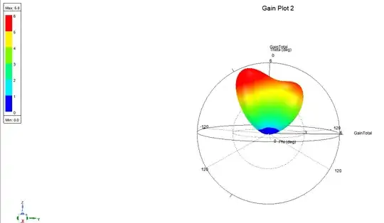
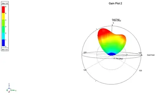
I am trying to design and understand a 30mmx45mm patch antenna. The setup is below, but it is a 50mm long, 50ohm T.L. feeding the patch antenna on Rogers5870 circuit board. I am trying to do impedance matching with an open circuit stub. My issue is two-fold: i) when I have a really good impedance match, where my S11 parameter is very low, my gain does not increase and ii) the 3dpolar plot is not symmetric. The details are below and I have attached the simulation file
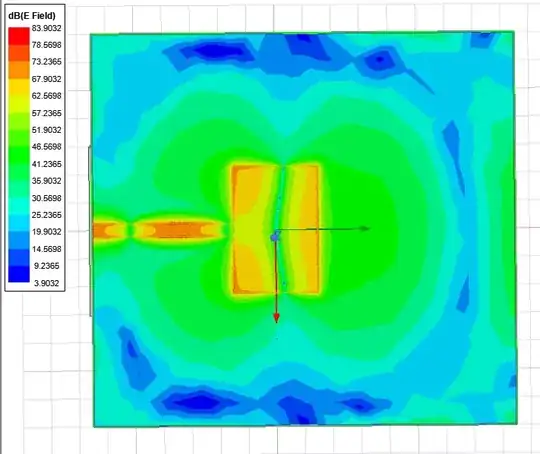
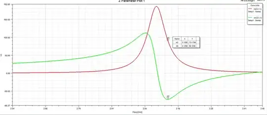
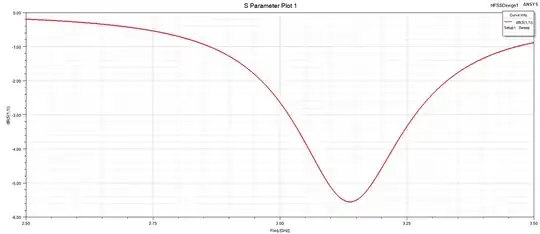
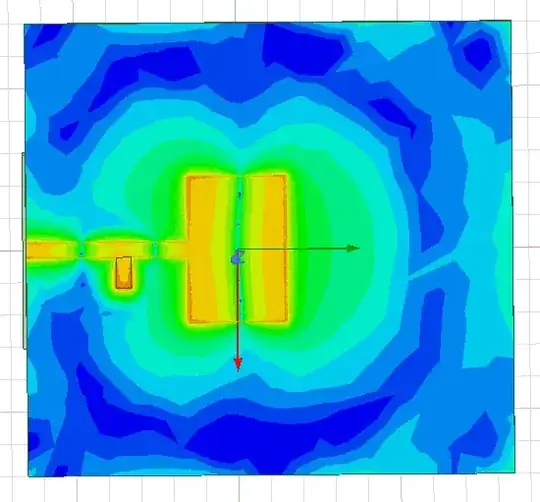
Case 1: No tuning stub--just patch antenna and transmission feed line The electric field plot and the 3d polar gain plot showing asymmetry, here the gain is 5.8dB and the S11 parameter at 3.125GHz is -5dB. I deembeded the excitation by 50mm to the entrance of the patch antenna to estimate what the impedance was and Re(z)=89ohms and Im(z)=-75ohms
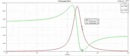
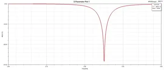
Case 2 included the tuning stub used for impedance matching As before, the electric field plot and the 3d polar gain plot showing asymmetry, here the gain is 5.8dB and the S11 parameter at 3.125GHz is now -37dB. I deembeded the excitation by 50mm to the entrance of the patch antenna to estimate what the impedance was and Re(z)=52ohms and Im(z)=-.6ohms which means the impedance matching is working quite well. My question is, why is my gain not improving?
