0

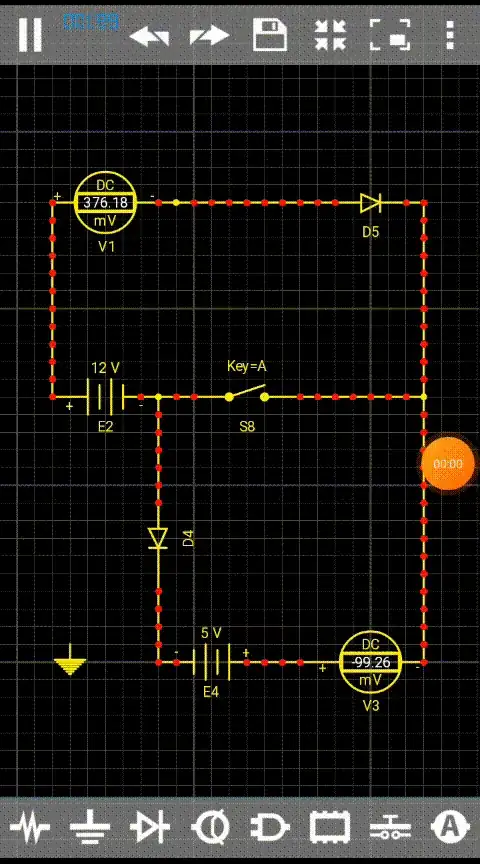
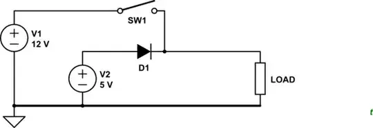
I have 2 DC sources 12V and 5V, I want to switch them using one switch as shown on scheme. I used here 2 diodes to isolate circuits and it works fine on simulation, but in real scheme 5V (actually rather 4.7V from USB) becomes 5.4V. How can I make circuits run independent (ie. they do not affect each other) in this case?

enter image description here

Simulation with open/closed switch - works fine on simulation but not in reality
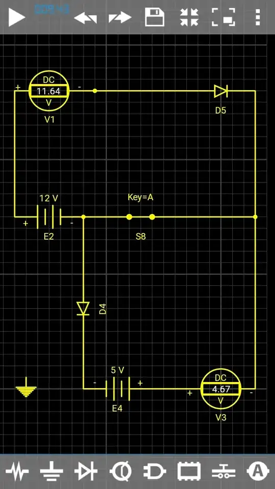
enter image description here

schmidt9
  • 105
  • 3
  • 2
    Why not simply use a DPST switch? – Unimportant Apr 24 '21 at 18:50
  • @Unimportant yeah it's a good point, but in real schema I have an SPDT Centre Off with an another circuit on the second switch position, so I have to bind these two circuits on the remaining position – schmidt9 Apr 24 '21 at 19:13

2 Answers2

2

schematic

simulate this circuit – Schematic created using CircuitLab

Figure 1. Using a single-pole normally-open switch to select '5 V' or 12 V supply.

  • SW1 open: 5 V is supplied to the load via D1. A silicon diode will drop 0.7 V. A Schottky diode will drop about 0.3 V.
  • SW1 closed: 12 V is supplied to the load. D1 prevents backfeed into the 5 V power supply.

schematic

simulate this circuit

Figure 2. Switch to disconnect two loads.

  • SW1 will disconnect the common return from both loads to the common ground at the power supplies.
  • D1 prevents V1 back-feeding into V2 when SW1 is open. It will cause a voltage drop in normal operation as described above.

This isn't an elegant circuit. Switching negatives in a negative ground circuit can lead to all sorts of confusion. It is, however, common on automobile circuits.

Transistor
  • 175,532
  • 13
  • 190
  • 404
1

Here's how, with the switch 'S1' being used to control the 12 V load and a 12 V electromagnetic relay to control the 5 V load.

enter image description here

vu2nan
  • 18,175
  • 1
  • 16
  • 47