0

I am trying to know if an air conditioning is ON/OFF (Daikin with only Wired Remote Control). I want to read its LED. The circuit is fed by a simple 17.8 V two wires from the machine. I've read the base of the LED respect to the GND, and both extremes are at 6.13 V when OFF and at 1.9 V one over the other when ON. I don't dare to interfere the circuit at all, but simply tell the state to a Shelly 1 relay to expose it into a HomeKit system.

In my really poor knowledge about electronics I understand 741IC, yet a bit old, could make the work, as it doesn't drain any current from the Vin and could simply connect the pin 7 (V+ pin) with pin 6 (Output pin) which I would directly connect to the SW pin in Shelly 1.

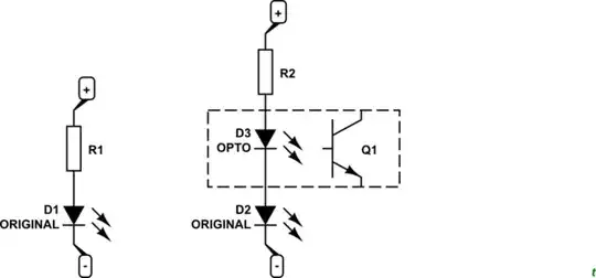
So the final scheme would be:

enter image description here

Would it interfere, could damage the AA circuit?

Transistor
  • 175,532
  • 13
  • 190
  • 404
  • 1
  • This is a "hookup", not a proper schematic, include a proper schematic if you want a decent answer. 2) This circuit is NOT going to do anything useful. You're treating the 741 as if it is a "ready to use" amplifier, it is not. You should a) not be using a 741 because it is ancient b) study opamp circuits to see how other use opamps and then do the same. If you, as a beginner, try to make your own circuit my guess is that you will destroy components and be frustrated that nothing works. So study what others do, then do the same.
  • – Bimpelrekkie Apr 03 '21 at 12:58
  • You should first read: http://web.mit.edu/6.101/www/reference/op_amps_everyone.pdf Then read this: https://electronics.stackexchange.com/questions/304521/reasons-not-to-use-a-741-op-amp to learn why no one should not use the 741 anymore. – Bimpelrekkie Apr 03 '21 at 13:01
  • You're right. I'm learning… quick and dirty programming has always worked for me… It seems I need a deeper change of habits – Juan Falgueras Apr 03 '21 at 13:16
  • quick and dirty programming has always worked for me Sure, for programming that can work, there's nothing to damage either. For hardware design, it is more complex. – Bimpelrekkie Apr 03 '21 at 13:55
  • I would try to either isolate myself from the circuit with an optocoupler, either on the input as per Transistors suggestion below or on the output. The 17.8 V you mention, is that available at all times in the remote control? Can you hook into it? If yes, I would place a comparator there to trigger on the LED voltage and drive an optocoupler on the output. Transistors suggestion has fewer parts though if you are willing to solder and/or cut into the existing remote. – winny Apr 04 '21 at 09:56
  • Great! powering of the wired remote (on a wall) is always on, as it displays permanently the AA state. So I think I can draw a few mAmps from it to source the Shelly (it's less than 1w always… with a ESP8266) and the LED sensor. The switch of that shelly will be used to short 0.5secs the on/off button connectors of the remote

    Thanks a lot for your idea, and the the CircuitLab link! This is really passionate!

    – Juan Falgueras Apr 04 '21 at 10:59