I have been banging my head on this puzzle for a few days now, need some help from the experts...
Here is the schematic of my first attempt at an H bridge for an RC car.
 The motors ( two in parallel) draw 2.5A max when stalling.
Vcc2 and Vcc5 are tied together, and so are Vcc3 and Vcc4.
I have tested every part of the circuit individually and it works just fine.
It also works fine when I test the two Half bridges separately.
However, when I put everything together I get all kinds of smokes coming out of the power transistors, and I have already fried a voltage regulator I am using to test before I hook it up to an arduino pro micro.
My feeling is that Voltage is travelling through the motor to the side that is suppose to be off and somehow turning it on, but I don't know how to verify that without blowing things up...
Any help or suggestion would be greatly appreciated.
The motors ( two in parallel) draw 2.5A max when stalling.
Vcc2 and Vcc5 are tied together, and so are Vcc3 and Vcc4.
I have tested every part of the circuit individually and it works just fine.
It also works fine when I test the two Half bridges separately.
However, when I put everything together I get all kinds of smokes coming out of the power transistors, and I have already fried a voltage regulator I am using to test before I hook it up to an arduino pro micro.
My feeling is that Voltage is travelling through the motor to the side that is suppose to be off and somehow turning it on, but I don't know how to verify that without blowing things up...
Any help or suggestion would be greatly appreciated.
- 103
- 5
-
I assume the bottom halves are connected to ground in the actual circuit BTW – user253751 Feb 16 '21 at 17:23
-
1At what point does smoke start coming out? When you wire the motor but don't turn it on? When you turn the motor on in one direction? When you start and stop the motor a lot? Does it still blow up if you use a 1k resistor instead of the motor? – user253751 Feb 16 '21 at 17:23
-
If I have both switches to ground, things already start getting hot, if I switch one side on smoke starts to come out. I am not really willing to do any more tests with the power on until I get some clues on what might be actually happening... – GiuBu Feb 16 '21 at 17:35
-
With motors around 10 Ohms and Rb= 470 Ohms ,this design has many problems as the transistors will not reach Vce(sat) and get fried. (assuming missing grounds were added – Tony Stewart EE75 Feb 16 '21 at 17:42
-
You said it works if you test both half-bridges separately. But it breaks when you connect the motor. That's why I asked if you put a 1k resistor instead of the motor. – user253751 Feb 16 '21 at 17:43
-
2You also say "both switches" but your diagram has 4 switches and none of them do anything, what's up with that? – user253751 Feb 16 '21 at 17:43
-
What’s controlling S1-S4? Show oscilligram/pattern. – winny Feb 16 '21 at 17:45
-
Both sides are turning on at the same time, and if you really do have multiple batteries, it could be that the voltage levels are not correct or the batteries are not wired properly. It could be that your ground is floating, choose a ground and then make sure everything from that ground is the proper potential – Voltage Spike Feb 16 '21 at 17:41
-
The switches are all powered from the same 5v supply, and everything is grounded to the 16V battery – GiuBu Feb 16 '21 at 17:43
-
1Not clear in you diagram, your diagram shows 4 batteries with no ground – Voltage Spike Feb 16 '21 at 17:43
-
To build on what @user253751 has written, if your schematic accurately represents your circuit, no current can flow through the 2.2k base resistors connected to the switches. – Math Keeps Me Busy Feb 16 '21 at 17:47
-
Both Half bridges work very well on their own, they spin the motor at full power without getting hot at all, even if I hold the wheels and force them to spin slowly to drive the amps up, no heat at all. If I connect the two halves together with the motor, I get this problem. I edited the schematics, hopefully it makes more sense now. Sorry I am not an expert at all. First schematic I have ever drawn. – GiuBu Feb 16 '21 at 18:02
-
BJT's are not a viable solution, you need to start over with FET's. Realistically do a web search for brushed motor ESC designs for RC car applications. – Chris Stratton Feb 16 '21 at 18:06
-
Can you please explain why? They seem to work just fine when not in an H-bridge configuration and they are rated for 12A. Plus they come from an old ESC for an RC car. – GiuBu Feb 16 '21 at 18:17
-
MOSFETs would definitely be the better choice but if you have BJTs on hand and just need to build something that will work they'll be fine. The transistors that you've chosen (B826 & D1062) can handle the load current you need. The base current you're supplying should be increased a little though which is probably why you're having issues. The way you're driving the bases is also a little over complicated. There's simpler ways to do it using fewer transistors and resistors. – Richard Thiessen Feb 16 '21 at 19:20
1 Answers
Your circuit diagram could use a bit of work, I'm assuming there's an additional ground attached to the negative terminal of both batteries since that's the only sensible place to put it. Your circuit is more or less correct though.
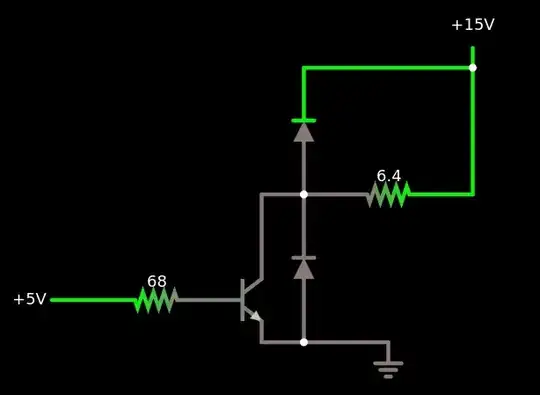
If you're going to use a power transistor, you have to read the datasheets (NPN,PNP). For BJTs you should be looking at the current gain and use this to calculate the required base current to keep the transistor from saturating for your worst case load current. Your worst case load current is 2.5A. You can see in the datasheet for both transistors that at an Ic of 2.5A the hFE is around 100 and 90 for NPN and PNP respectively. Using the 100 value that means at least 25mA of base current will be required. In practice double that to be safe. The graphs show typical values and your transistor might have a lower hFE. If there's too little base current, the transistor won't be fully on and will go into linear mode. Voltage across it will increase and it will pop and release the magic smoke. Using a 470 ohm resistor you're getting about 34mA of base current which is uncomfortably close to the 25mA minimum A 330 ohm resistor would be better.
Before you build the full H bridge, you should check that your power transistors can handle the load current they will experience in circuit. You should build a test circuit and verify that everything works.
But wait, there's another thing you should really be doing, I assume for your project you need to run the motor in both directions and also have the ability to brake or freewheel. You can save power consumption and simplify your circuit by directing base current out of the high side BJTs and down into the low side BJTs.
link
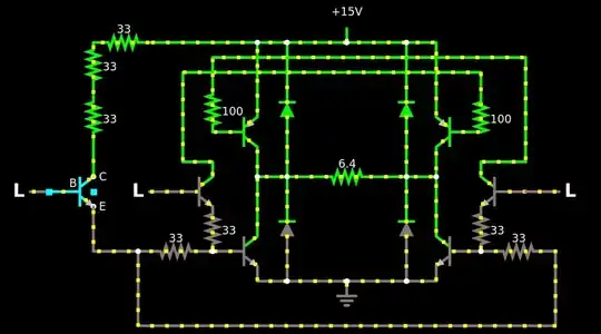 Note that you can press the "L" labelled inputs to toggle them from low to high or vice versa.
The two logic inputs next to the bridge run the motor forwards and backwards, the one off to the side turns on both low side transistors to brake the motor.
The logic inputs are set for 3.3V. For 5V operation replace the 33 ohm resistors with 68 ohm resistors. The 100 ohm and string of three 33 ohm resistors are there to reduce power dissipation in the smaller control transistors. Otherwise they would have to drop nearly 12 volts and power dissipation would be much to high for a common TO-92 packaged BJT.
You should also add a 100 ohm resistor between the microcontroller and the logic inputs in the above circuit. This limits microcontroller pin current to below 20mA if the 16V supply is not present preventing damage to the MCU.
- 503
- 3
- 4
-
Wow , thank you so much for the detailed explanation. I have substituted the 470 ohm with 200 ohm( that's what I have at hand) and everything works perfect. Your suggested circuit look much more lean then mine of course, like I said this is my first attempt, and I am working things out as I go along, perfect recipe for delicious blue smoke I guess... – GiuBu Feb 17 '21 at 04:00
-
But if I drive just the two logic inputs close to the center, that should be enough for forward, reverse and brake. Am i wrong? – GiuBu Feb 17 '21 at 04:07
-
Just to clarify, driving the two middle inputs at the same time will turn on all four transistors and short circuit the battery through the bridge so don't do that if that's what you're asking.
You don't need the brake state and having it gives you no better control over the motor theoretically. The two inputs you mentioned give you +B and -B applied voltage. the third applies 0 volts which makes it easier to achieve low power drive since for PWM you can alternate between 0 and +B or 0 and -B rather than -B and +B (which makes getting exactly the voltage you want more challenging/noisy).
– Richard Thiessen Feb 18 '21 at 03:03 -
So, if I understand you correctly, the third input would have the same function as an enable pin on a h bridge Ic, where you would pull one side high and the other low and PWM the enable pin? Sorry for my ignorance, but I don't understand your point about +B and -B. The way I figured it, but haven't tried yet, is to pull one side low and PWM the other. – GiuBu Feb 18 '21 at 07:30
-
Also I did try to pull both side high on the circuit I made based on my schematic and your suggestions, I have read somewhere that's how you can brake the motor, and the motor did stop very rapidly. However, after a few seconds of keeping both inputs high, I noticed a little bit of smoke coming from one of the transistor, so I guess I won't be doing that again... – GiuBu Feb 18 '21 at 07:33
-
When I say +B and -B I mean applying the battery voltage across the load in the forward and reverse directions (IE:the voltage applied to the motor measuring from one terminal to the other). What most people refer to as the brake state of the bridge applies 0 volts to the motor by turning on either the top two or bottom two transistors. If no transistors are turned on the bridge is in the "high impedance" state and will act as a rectifier, opposing movement of current with the full battery voltage. – Richard Thiessen Feb 19 '21 at 06:37
-
Turning on both high side transistors shouldn't cause any problems. The smoke might have been coming from your resistors. A 200 ohm resistor with 16 volts across is dissipates more than 1 watt. If you're using standard 1/4 watt resistors, those will die pretty quickly. If you want to be sure about it though, just disconnect the motor and try it again. That will let you test everything but the power transistors. – Richard Thiessen Feb 19 '21 at 06:42