I am troubleshooting a relay driving board that uses an MIC5891 to drive a 12VDC relay (86Ω coil). The load supply voltage into the 5891 is 12V. When checking an output with no load I get 12V. When I put even a small load on the output (115ma measured), (it can handle 500ma) the voltage drops to 10VDC, but the input supply voltage still stays at 12V. All the other outputs are off, so I'm not overloading the driver. Why does the output voltage drop with a minimal load?
-
2How about a schematic of your relay coil driving circuit? – jwh20 Feb 11 '21 at 15:28
-
@Mike, you've unaccepted my answer. Is there something you wish to discuss? – Andy aka Feb 15 '21 at 14:28
2 Answers
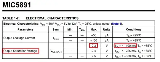
Look at this table in the data sheet: -
It basically tells you that with a 100 mA load current, the chip may "lose" some 2.3 volts in its output transistor thus lowering a 12 volt power supply to about 9.7 volts on the output.
Of course that's the maximum value of "lost voltage" so if you see 10 volts at 115 mA then that doesn't really surprise me: -
When I put even a small load on the output (115ma measured), (it can handle 500ma) the voltage drops to 10VDC, but the input supply voltage still stays at 12V.
The good thing is that you double checked that the supply hadn't changed in voltage.
- 456,226
- 28
- 367
- 807
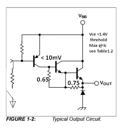
The design is a BJT with a Darlington output so you lose 1.4V from Vcc until it can conduct current due to Vbe=0.7V*2.
The output impedance is then the internal driver impedance to the Darlington Rout=\$R_b / h_{FE}^2\$ (approximately) but Rb is undefined so we can estimate output impedance Rce from table 1.2 of rising in saturation voltage / rising load current. I call this saturation output impedance Rce.
(2.3V-1.4)/100mA= 7 Ohms = Rce equivalent estimate at 85'C
(2.5V-1.4)/350mA= 3.1 Ohms
Thus an 86 Ohm coil will see a voltage determined by KVL with this characteristic.
I suggest you define specs for your design then change either specs or design to match.
- 1
- 3
- 54
- 185

