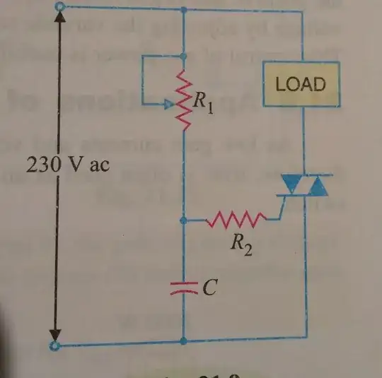
It's a triac phase control circuit, my book says. I know the conduction angle or the firing angle can be adjusted by adjusting the gate current in both cycles. but the question is what is the purpose of the capacitor here? How it's controlling the gate current?
-
5Think it through. So if you were to plot the source voltage and the voltage at the junction of C and R2, what would it look like? – jwh20 Feb 08 '21 at 15:53
-
@jwh20 but the voltage (hence current) across r_2 is not constant right? So how the gate current is held constant? – Sayan Feb 08 '21 at 16:20
-
1The gate current isn't held constant, where did you get the idea that it might be? – Neil_UK Feb 08 '21 at 16:36
-
1I don't see where anyone said the gate voltage/current is constant. That's why I said "plot" and not calculate. – jwh20 Feb 08 '21 at 16:36
-
I understood everything now. Thanks – Sayan Feb 08 '21 at 17:19
1 Answers
This is a standard light-dimmer circuit. In fact it's almost perfected using a DIAC on the gate to obtain even triggering (a DIAC is a semiconductor that triggers when the voltage reaches a certain voltage and unlatches when current goes back to zero).
The trick is somethink like this: the RC networks changes the phase of the input voltage, so the nominal trigger current reaches the gate at a different time than the load one at the main terminals. Of course, it has problems with inductive loads. Also there are transient issues so a snubber could be needed, depending on the triac type. And the harmonic distortion of a phase trim regulator like this is horrible, so these days is not used very much.
But it's really simple and cheap, so it has it uses.
https://www.homemade-circuits.com/how-triac-phase-control-works/ has some more explanations and some useful modification to the base circuit. Search for triac 'phase control' gives a lot of resources, in general
- 8,431
- 8
- 30
