24

I am using a blue LED (InGaN) in a simple circuit to show me when my garage door is opened by looking through a window.

The door is usually closed and may get opened once per day for a couple of minutes but sometimes longer.

The LED will work for 1-2 months then stop. I replace it and then the same thing happens.

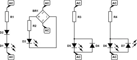
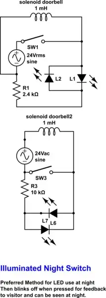
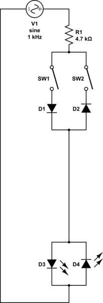
The circuit includes a blue LED in series with a 4.7K Ohm resistor, a 120VAC/24VAC transformer connected to 120 VAC source, a normally-open magnetic switch that closes when the garage door opens, and a fuse. The picture included does not show the transformer or the fuse.

As far as I can tell, I am not exceeding any design limits of the LED including temperature.

Any ideas?

enter image description here

JRE
  • 71,321
  • 10
  • 107
  • 188
Beamish Boy
  • 369
  • 2
  • 3
  • 17
    Note Vrev =-5V max . Use two LEDs back to back to block neg V – Tony Stewart EE75 Jan 28 '21 at 20:11
  • 7
    Sure you are. As Tony said, you are applying more reverse voltage than it can handle. Why are you using 24 Vac in the first place for the LED? – winny Jan 28 '21 at 20:13
  • 2
    @winny - 24Vac is a common voltage supply for garage door opener remote control receivers. Presumably it is already available. – Kevin White Jan 28 '21 at 20:18
  • 1
    You may need over voltage protection as there might be more than 24V on the circuit at times – Voltage Spike Jan 28 '21 at 20:20
  • 2
    using 24VAC because I had a transformer that was readily available. Sounds like I i'm over driving it. Thx – Beamish Boy Jan 28 '21 at 20:27
  • 1
    Can you replace your transformer with a DC output power supply instead? Otherwise any of Transistors proposals below will work. – winny Jan 28 '21 at 21:44
  • 1
    @BeamishBoy It could be a good use for an old USB phone charger. – Andrew Morton Jan 29 '21 at 10:49
  • 4
    Yeah, the problem is the resistor is dropping 0 volts in reverse current. Because it's a diode, there is no reverse current, so resistor voltage drop is 4700 ohms x 0 amps = 0 volts drop. 24V RMS - 0V drop = 24V RMS against the diode. – Harper - Reinstate Monica Jan 30 '21 at 01:58

4 Answers4

61

Any ideas?

Yes. You are feeding the LED with an AC supply. That means that every second half-cycle it will be reverse biased. Most LEDs can withstand about 5 V in reverse. You're applying 24 V AC which will have a peak voltage of \$ 24\sqrt 2 \ \text V \$ so I'm surprised you got any length of time out of it.

You have at least four options:

schematic

simulate this circuit – Schematic created using CircuitLab

  1. Add a diode in series.1
  2. Add a bridge rectifier.
  3. Add a diode in reverse parallel with the LED.1
  4. Add another LED in reverse parallel with the LED.2
  • 1 LED will be half brightness for a given resistor value as only positive half-waves will light the LED.

  • 2 Each LED will be half brightness for a given resistor value as only positive half-waves will light one LED and negatives the other.


Technical note

Strictly speaking, the first diagram relies on most of the reverse voltage being dropped across D2 while D1 remains at < 5 V. What happens in practice will depend on the reverse leakage current of both devices and the one with the lower leakage current will experience the highest reverse voltage. This would require a dig through the datasheets for both devices.

Transistor
  • 175,532
  • 13
  • 190
  • 404
  • 6
    On SE sites you hit the "Accept" button on the left if there's an answer that solves the problem. Otherwise the system keeps bringing the question up for an answer. You can also upvote other answers. – Transistor Jan 28 '21 at 22:28
  • 1
    Presumably in option 1 you'd need a diode with Vrev>=30V. In particular, a LED is by definition a diode, and you can't reliably solve the problem by putting two of these blue LED's in series. (Although the failure rate would likely drop sharply) – MSalters Jan 29 '21 at 13:23
  • 1
    Some 1N400x would work fine. – Lundin Jan 29 '21 at 13:51
  • 3
    I just remembered that when I graduated in '75, I put a GaAs LED with my 24V doorbell switch and it got dimmer after a few yrs when we moved out. It blinked when released from the flyback solenoid then stayed on. Tough little diode. – Tony Stewart EE75 Jan 29 '21 at 14:14
  • 1
    How do you find the switch in the dark? – Tony Stewart EE75 Jan 29 '21 at 14:43
  • 2
    @MSalters that's going to be any normal diode though, no need to look for a special one, feel free to double-check it if you're worried – user253751 Jan 29 '21 at 19:09
  • Your "first" (leftmost) solution could be made more reliable by adding a high-value resistor in parallel with the LED, D1. – Solomon Slow Jan 31 '21 at 23:48
7

schematic

simulate this circuit – Schematic created using CircuitLab

The solenoid current will produce a pulsed current when released so a greater R value is preferred. Most of the voltage drop is across R with V=LdI/dt. (which can reach HV )

  • next time you have a spare LED to use this to also protect against ESD damage in circuit or from small flyback currents.
Tony Stewart EE75
  • 1
  • 3
  • 54
  • 185
  • 3
    From very small flyback currents. I would never recommend an LED in place of a proper flyback diode. The latter are designed for purpose, LEDs are not. Yes, they are both diodes, but flyback diodes can take significantly more punishment - and in a flyback application they will receive that punishment. – J... Jan 29 '21 at 15:40
  • 3
    I used to correct my Prof's all the time. I guess this is payback senior's moment ..doh .. at least someone is paying attention, kudos. – Tony Stewart EE75 Jan 29 '21 at 20:58
7

Got anything else to monitor? Detect 2 things on 1 cable

Which works because this is AC.

schematic

simulate this circuit – Schematic created using CircuitLab

Note that we're depending on each diode to be working to protect the other from reverse current. If D3 failed with SW1 closed, no current would flow, so R1 would drop no voltage, and D4 would get smacked with 24V RMS. The only way to fix that is another guard diode right next to each LED.

Also, you'd need to make the diodes different colors, and they might have different forward voltages, so a resistor above one of them might be necessary.

-1

Gotta get some voltage drop in the series resistor when the diode is back biased. Another way not mentioned above is to hang a parallel resistor across the diode. Calculation of the values is left as an exercise for the student. :-)

richard1941
  • 670
  • 4
  • 7