If I wait some time, the base current becomes 68uA and the emitter
current 1.4mA.
This suggests a capacitor in the circuit is taking some time to charge up to a stable DC voltage. In your schematic C1 = 100 mF. This is a very large value (1/10th of a Farad!). 100 μF would be more reasonable.
I simulated your circuit in LTspice using a BC547B (which has HFE of ~300). Here is a plot of Emitter and Collector voltage during the first 200 seconds after switch on.
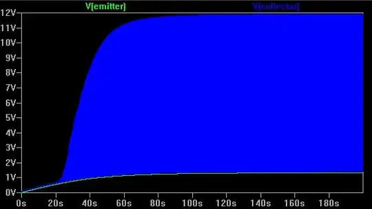
It takes over 20 seconds for the Emitter voltage (green line) to rise enough to get the transistor out of saturation, and over 100 seconds to reach a stable voltage. The Collector voltage (which looks like a solid area due to the high signal frequency) shows that the input level is too high, causing the output to bang against the supply rails as the transistor turns fully on and off.
The plot below shows Base current (green), voltage across C2 (red) and Collector voltage (blue) over a few cycles of the signal:-
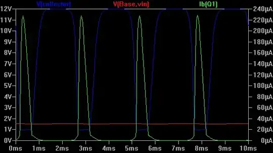
The input signal is so high that the Base-Emitter junction is acting as a rectifier, charging C2 with negative current which reduces the Base bias voltage from ~2 V to ~1.5 V. The output waveform is strongly clipped on both positive and negative peaks, causing massive distortion.
After reducing the input level from 0.125 V to 0.0125 V, it looks much better:-
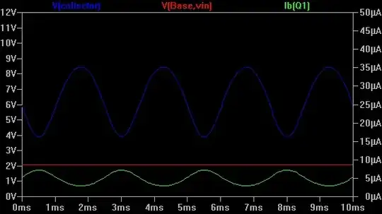
Now the Base current is continuous (with negligible rectifier action), Base bias voltage has returned to normal, and the output waveform only shows a small amount of distortion.
Why are calculation and simulation so different? Are my calculations
wrong ?
Your calculations are based on a small signal level which doesn't cause significant distortion or change the DC bias level. It also assumes that all capacitors are charged to their final DC values.
When simulating a circuit with potentially large AC voltages it always pays to inspect the waveforms. Average, rms, peak and DC values do not tell the full story and can be hard to interpret.
If some elements may cause significant time delays then simulate for long enough to ensure that the circuit has stabilized. If this takes too long then either change component values to reduce the delay, or set the required initial conditions to skip it. be aware that simulating a small time period may give misleading results.


