We are making a rotating machine where we need to measure the flux in the air gap, however, the flux sensor is too thick to fit in the airgap so a slot will need to be cut into the face of the pole so the flux sensor can slide into it.
But before we do that, we need to determine how much those modifications will distort the flux readings so I was going to make a mock-up.
There would be two setups:
- The control setup would consist of a UI core with a DC-excited winding and an air-gap machined into it that would fit the thickness of the flux sensor.
- The second setup would be identical except it would have a slot machined into one face of the airgap that the flux sensor could rest in.
Then we would compare the readings of the flux probe at the same DC excitation. Our only goal is to see how much a slot would throw off the flux readings of the flux in the air gap. In this mock setup, we can make the airgap large enough to fit in the flux probe to compare, but on the actual machine the airgap is too small so we would have to make an inset/slot for the flux probe to nestle into but we have concerns about the slow affecting accuracy.
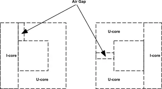
My question is this: Does the location of the airgap in the middle or at the corner of the core matter? Because if the airgap could be at the corner, we could put the coil on a bobbin and on to an I-core and move it back and forth between the two setups (an unmodified U-core and a U-core with an airgap machined into it), rather than needing to wind two separate cores.
I suppose we could do it share a bobbin and coil either way, but if the airgap should be mid-length then that's three fiddly pieces and we might choose against that.
simulate this circuit – Schematic created using CircuitLab