Background
I'm working on application that I think the LP2950-50 would be appropriate for. I want to control a set of SSR 40 DAs from the GPIO pins of a raspberry pi. Empirically, I've found that 5V applied across Vin of the SSRs works best to close AC side. I don't want to use the 5V out from the Pi, so I'm trying to build a power supply circuit that sends current from a LP2950-50 to the SSR (using an LDO per SSR). I'm using a 2N2222 NPN transistor per GPIO pin to control current flowing from the LDO to the SSR. I've built a prototype of this circuit, and it works. I can control the SSRs as intended. The circuit is an array of the following (one per SSR):

The problem
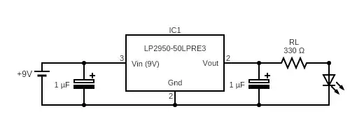
I'm not consistently measuring the expected voltage on Vout of the LDO. What I have observed is that if I increase the impedance of the circuit between Vout and Gnd, the value I measure between Vout and Gnd increases. This seems contrary to the datasheet which suggests that I should be getting ~5V out regardless of the load applied to Vout. I've been able to get the LDO to produce the expected voltage, but only by finding a resistor of appropriate size. ~1KOhm between Vout and Ground seems to do it. I'm able to replicate the issue with the following simple circuit.
When I measure potential across the resistor and LED, I'm only seeing ~3.25V. If I increase the size of RL to 1KOhms, the voltage across RL and the LED increases to 5.5V. I can swap in a brand new chip and get the same result.
What I've tried
Various capacitors. I'm using a 1uF tantalum capacitor with an 8 Ohm ESR rating. Per the datasheet, the ESR value may be too much. Should this out-of-spec ESR produced the results I'm seeing? I also tried a 1.5uF ceramic capacitor hoping it would have an ESR between the minimum of 20-30 mOhms and 5 Ohms. It produced the same result: need to vary the impedance across Vout and ground to get the desired voltage. I am not yet capable of measuring the ESR of the ceramic resistor. Aside from ordering another pack of caps with known ESR that's in range (or trying another sized capacitor), I'm about out of rope on this. Any thoughts on anything to try next? Apparent design flaw on my part? Or maybe the chip is working as intended and I should let it go.
Edit after answer:
I was reading the pin-out incorrectly on the datasheet. After inserting correctly I can measure the expected voltage, even with an out-of-spec capacitor. When supplied a 60Hz square wave signal from the Pi GPIO the LDO continues to perform well. It continues to deliver a 5V signal on Vout despite an out-of-spec capacitor.
Notes:
- I've calculated the internal resistance of the SSR to be ~400 Ohms via Ohms law.
- LP2950 Datasheet: https://www.ti.com/document-viewer/LP2950/datasheet
- Capacitors (TAP105K035CCS) datasheet: https://www.mouser.com/datasheet/2/40/tap-776819.pdf
