0

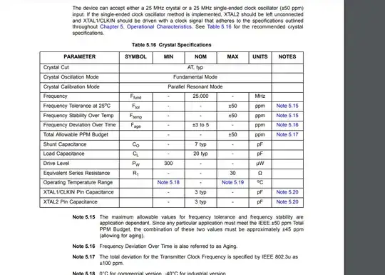
I am designing an Ethernet circuit ( my reference design is the Ethernet circuit in stm32f767 nucleo). The crystal drive level required by the Ethernet transceiver (LAN8742A/LAN8742Ai) is 300 uW. LAN8742A DATASHEET

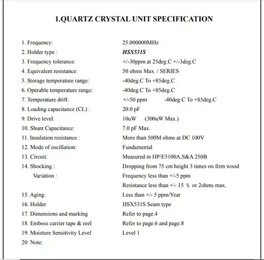
I will manufacture the board at JLCPCB. I didn't find 25.000MHz crystal with the required drive level in their SMT parts library.I found this one X1H025000FK1HA-X with 300 uW max level drive. Crystal Datasheet

My question: Can I use it? enter image description here enter image description here

PCB-ABBS
  • 176
  • 1
  • 13
  • 1
    There are no guarantees but I think you have a 99.9% chance that this crystal just work fine. Most crystals aren't that different from eachother. The crystal oscillator circuit in the LAN8742 will also be very "generic", I mean the same as almost every microcontroller and CPU will use. In the past I have used many different crystals most of which do not even have a drive level specified so I just ignored the drive level and every time the oscillator just worked. Only if this is a design for mass production would I ask the manufacturer of the LAN8742 what crystal they recommend. – Bimpelrekkie Nov 13 '20 at 13:19
  • 1
    You probably don't want to confine yourself to their stock parts. Pick something available in your lociation with the needed specs, put the proper footprint on the board. Either get them to buy what you need, go through the hassle of shipping them the parts if it's a high quantity build, or more likely just install the one part yourself upon receipt if its a small prototype batch. Though if the IC is their stock part, you might legitimately ask what they expect people to use with it! – Chris Stratton Nov 13 '20 at 15:40
  • 1
    As you're discovering, small crystals that can dissipate much power are hard-to-come-by. You might have more choices with larger crystals if fragility is not an issue. At 25 MHz, AT-cut crystals are thin. – glen_geek Nov 13 '20 at 19:49

2 Answers2

2

My question: Can I use it?

No, you can't because the LAN chip delivers higher power levels into the crystal to obtain better regulation at the oscillation frequency. Note that the chip specifies a loading capacitance of 20 pF and that means 40 pF each side of the crystal to ground and, the knock on effect of that is that frequency stability improves. Take a look at this picture to begin to understand why: -

enter image description here

What the picture shows is a typical 10 MHz crystal (20 Ω ESR) with various loading capacitances from 2 x 5 pF (net CL = 2.5 pF) to 2 x 40 pF (net CL = 20 pF). Of particular interest is the phase response of the crystal (the lower picture) because with 40 pF capacitors, the frequency is less ambiguous (the graph is steeper) as it passes through 180° phase.

This means that the crystal overall (in its oscillator circuit) will have less drift due to temperature effects on the silicon altering the frequency of its 180° phase-point. So the crystal produces 180° and the silicon (aka inverter) produces 180° and you get an oscillator.

The bottom line is that with higher CL you get better stability but you inevitably drive harder and that means more power dissipated in the ESR of the crystal. There is of course some danger that more power dissipation in the crystal can lead to crystal drive frequency changes but this will be smaller than the effects of the inverter used in the typical pierce oscillator circuit altering its propagation time with temperature. But it can be a trade-off.

So, choose a crystal that can work with 2 x 40 pF loading (net = 20 pF) and can survive (without detriment) the power levels. In the example above, if the voltage drive level were 4 volts p-p, the power when CL = 20 pF would be around 300 μW.

Picture from here.
Andy aka
  • 456,226
  • 28
  • 367
  • 807
1

No, the crystal can have ESR up to 50 ohms and the chip requires a crystal with ESR only up to 30 ohms.

Justme
  • 147,557
  • 4
  • 113
  • 291