The output of the 555 is either high or low. If it is high the bottom LED will light, if it is low the top LED will light. So whatever state the 555 is in, there's always one LED on.
There's other problems with this circuit. A 555 cannot handle the mentioned 60V for example.
I'd forgo the 555 altogether and make something discrete:
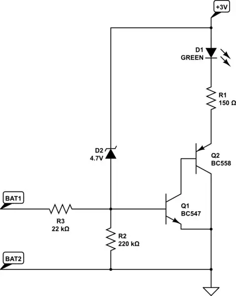
simulate this circuit – Schematic created using CircuitLab
It uses 2 transistors configured as a Sziklai pair for high gain while avoiding the double B-E junction voltage drop of a regular Darlington, because we cannot afford the voltage drop with the 1V minimum requirement.
Because of this high gain there is still enough base current trough the 22K resistor to light the LED even at the 1V minimum while still not allowing excessive current in the 60V case.
Zener diode D2 prevents the base voltage from going too far negative in case a high voltage battery is under test in the wrong polarity.
R2 makes sure the transistor is off in case nothing is connected to test terminals.
A second circuit with a RED led can be built with the test terminals reversed to work in the opposite polarity.


