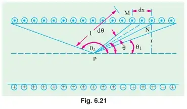
Reference I will refer to is Textbook of Electrical Technology by Theraja, page 268 (iv) Magnetising Force on the Axis of a Short Solenoid
The derivation is already there. I just don't understand the visuals that well because they look so complicated. I don't get the use of the variables clearly such as the θ, dx, θ1, θ2, r, and l and even the points M, N and P. Recently I have already studied and understood (iii) Magnetising Force on the Axis of a Circular Coil. But what I don't get is why they have to use that on this part even though this is about a short solenoid. It's not even circular. I am already lost with the whole, use the circular coil thing. I understand the idea of using differentials to represent infinitesimal values but the situation this time feels so complicated.
I mean, the derivation is already there and pretty clear for someone else who probably understands the topic. I just want a more clear explanation, especially on the visuals and how it relates to the Circular Coil geometry.

dx, I think they finally convert it todthetaso that the integration becomes easier. – AJN Aug 30 '20 at 04:11total turns / total lengthcircular coils per unit length). So the formula for the circular coil is used as the basis for deriving the magnetising force for the solenoid. The circular coil formula takes care of the integration around a single[sic] loop. What is remaining is to integrate the expression over all the loops, which is equivalent to integrating over the length of the solenoid. – AJN Sep 02 '20 at 04:55allloops. The solenoid is like havingNnumbers of single loop coils which are evenly spaced within a length ofl. – AJN Sep 02 '20 at 05:52