1

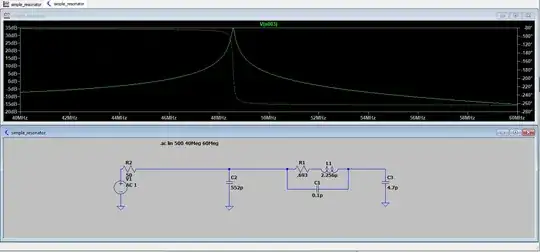
I am modeling a simple impedance-matched RLC series resonator. I get a nice resonance at around ~48.5MHz when I do an ac analysis. However, when I try to do the corresponding transient analysis at the resonant frequency, I don't see the ~35bB voltage gain. All waveforms are across the 4.7pF capacitor.

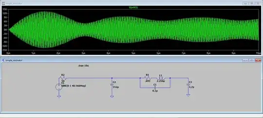
In fact, I don't really understand what I'm seeing in the transient analysis at all. Can you spot anything wrong?
enter image description here

C

2 Answers2

2

The envelope modulation indicates and error on the input frequency with T =3us

While the spectrum indicates a bandwidth of around 100 KHz.

Try a 1ms/MHz sweep around resonance.

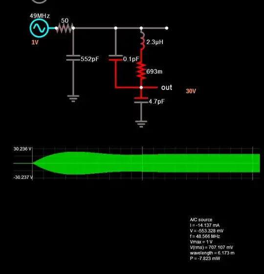
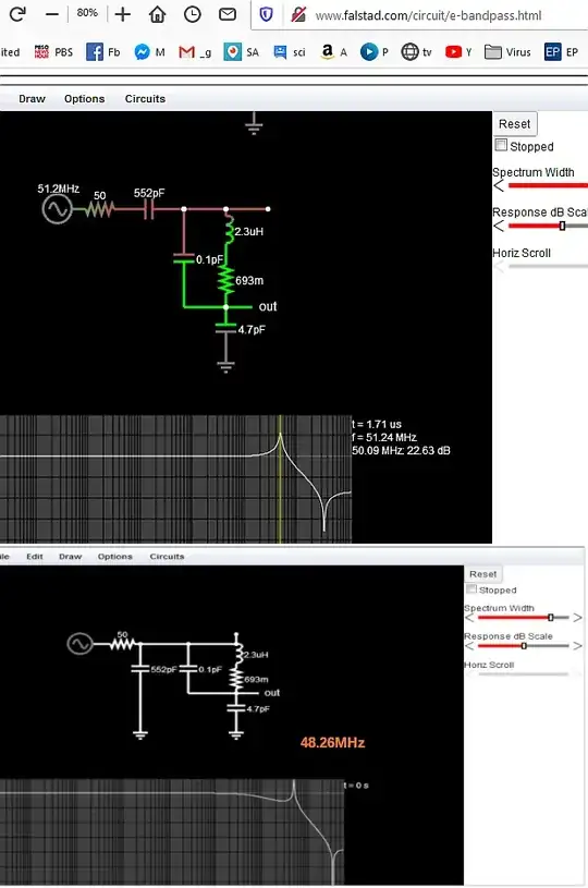
Simulator Alias error on display is my guess. but works on Falstad

However, your filter shape is non-std. and there are no specs.

enter image description here

enter image description here

Other comments:

Is the 0.1pF accurate or a roundup truncated?

The initial ripple envelope is due to the high Q response from the step amplitude on the carrier at startup and not the actual sweep response, so the high Q boosts the initial amplitude from step amplitude broadband energy superimposed on the carrier.

Did you really intend to have a notch? This is the classic series-parallel C//RLC//C xtal or ceramic resonator type response albeit not same results.

It is better to define the filter specs first.

Tony Stewart EE75
  • 1
  • 3
  • 54
  • 185
  • Thanks for the response. Any way to avoid the envelope? Why am I not seeing the 35dB voltage gain? – D. Zambrano Aug 15 '20 at 01:58
  • Do what I said to realize the correct frequency. – Tony Stewart EE75 Aug 15 '20 at 02:00
  • 2
    Tony, that was my first thought too (wrong frequency). But ran a simulation with a very fine timestep at 48.566 MHz, and got a good, high amplitude. – glen_geek Aug 15 '20 at 03:02
  • why should the frequency be different compared to the one I found in the ac analysis? It's the exact same schematic, right? @TonyStewartSunnyskyguyEE75 I did the sweep (with the help from this thread https://electronics.stackexchange.com/questions/291721/how-to-implement-frequency-sweep-in-transient-mode-in-ltspice) and got a peak in the transient analysis around 48.17MHz. However, when I go ahead and run the transient analysis (without a sweep) with this new frequency, I don't get the high amplitude. – D. Zambrano Aug 15 '20 at 03:28
  • @glen_geek did you get a high amplitude at 48.566MHz with a transient analysis? – D. Zambrano Aug 15 '20 at 03:30
  • Hmm I tried it on my Sim and it worked. Perhaps sort of alias effect undersampling with sweep rate and number of pixels. http://tinyurl.com/y5m6hmkk gain of 13.691 – Tony Stewart EE75 Aug 15 '20 at 03:31
  • Thanks Tony. The 552pF capacitor is not in series with the source. It should be in parallel. – D. Zambrano Aug 15 '20 at 03:40
  • oops watching TV at the same time.... http://tinyurl.com/y2ncl9nm – Tony Stewart EE75 Aug 15 '20 at 03:46
  • But I only got 23 dB gain – Tony Stewart EE75 Aug 15 '20 at 04:06
  • Change the freq to 48.46M @TonyStewartSunnyskyguyEE75 – D. Zambrano Aug 15 '20 at 04:23
  • What are your design specs? BW etc – Tony Stewart EE75 Aug 15 '20 at 07:04
  • I just need the highest possible voltage gain. For this I need a very high Q inductor and very good impedance matching. The load is just a 4.7pF cap. BW, etc, not really that important. – D. Zambrano Aug 15 '20 at 13:53
  • You also need tolerance specs, freq value and temperature stability with tuning and high Q reactance parts – Tony Stewart EE75 Aug 15 '20 at 14:22
1

What @glen_geek means in the comments is to impose a timestep. If you zoom in on the waveform you'll see it's jagged, and if you right-click on the waveform window and select View > Mark Data Points you'll see that the waveform is sparsely sampled. Try .tran 0 25u 0 0.1n, or even 10p, and you'll see a radical change. This happens because you have no load and the circuit is extremely simple and linear, so the solver can fly over it. As a general "rule of thumb", if you want precision, you need to impose a timestep.

a concerned citizen
  • 21,445
  • 1
  • 23
  • 40
  • 1
    Thanks for the ",tran" correction (editing that comment timed out). I've imposed a general rule on myself to choose a time-step that's a tiny fraction of a cycle on repetitive waveforms. If you're testing oscillators, timestep can influence oscillator frequency. – glen_geek Aug 15 '20 at 12:13
  • 1
    That worked! Thanks a lot! I guess the only mystery remaining is the following: Why is Tony's circuit in tinyurl.com/y2ncl9nm exhibiting the largest voltage gain at 48.46M instead of my circuit at 48.566M? Not that really matters that much, since I will probably measure something slightly different from either of these frequencies with the actual circuit. – D. Zambrano Aug 15 '20 at 13:34
  • @D.Zambrano It probably has to do with the number of points for the simulation. It could also be that LTspice has some default series resistance of 1 mOhm for uncoupled inductors, and some parallel resitances, but those values shouldn't interfere by that much. Whichever answer you think solves your problem, be sure to mark that one with the check mark, so that others, in the future, searching for similar problems, will see this question with an accepted answer. – a concerned citizen Aug 15 '20 at 17:12
  • @aconcernedcitizen Done. Thanks a lot! Amazing feedback and insight from everyone :) – D. Zambrano Aug 15 '20 at 17:20