I have a circuit where a 3.3V MCU which is not 5V compatible needs to drive an MCP23017. The MCP23017 will drive and read inputs and outputs from various 74HCT components. I'm thinking that based on the datasheet for the MCP23017, I can power it at 3.3V so it's communication to the MCP is 3.3V compatible. It would also put out logic HIGH at close to 3.3V but that is sufficient for the HCT parts to recognize as HIGH. I would power the HCT parts at 5V. Their outputs would be 5V for HIGH which, I believe, can still be read by the MCP23017 safely even if only driven at 3.3V. No bi-directional level shifter needed on the I2C lines?
Asked
Active
Viewed 531 times
1
-
The maximum input voltage to the MCP23017 is VDD + 0.6V, so if you are running the MCP23017 at 3.3V, the maximum you can put into an input pin is 3.9V. – Ron Beyer Aug 13 '20 at 14:27
3 Answers
1
No bi-directional level shifter needed on the I2C lines?
The I2C pins do not need a level shifter, as long as the MCP23017 and the MCU are both run at 3.3V, no level shifting is required since they are both operating at the same levels.
Their outputs would be 5V for HIGH which, I believe, can still be read by the MCP23017 safely even if only driven at 3.3V.
You will need to level-shift the inputs to the MCP23017 that are 5V though, since the 23017 can only handle VDD +0.6V, or a maximum of 3.9V. To do this, you can use a simple resistor-divider. You should size this such that the input is 3.3V, not 3.9V since 3.9V is an "absolute maximum" rating and may damage the device or severely reduce its lifetime.
Ron Beyer
- 2,578
- 1
- 10
- 22
-
1It would make more sense for him to run the MCP23017 at 5 V and have the level shifter between it and the MCU. Far less level shifters are needed that way. – evildemonic Aug 13 '20 at 15:07
-
@evildemonic I guess it depends on how many inputs are being used versus outputs. You may also have to consider board space, a BJT type bi-directional level shifter may take more space than a couple 0402 or 0608 resistor networks. – Ron Beyer Aug 13 '20 at 15:15
0
If you power the MCP23017 with 3.3 V, the pins are only tolerant to 3.9 V.
This is shown on page 3 of the datasheet under "Voltage on all other pins..." which shows Vdd + 0.6 V.

So, you need a level shifter. Here is an easy way to do it using MOSFETs that should work with most logic-level N-MOS devices:
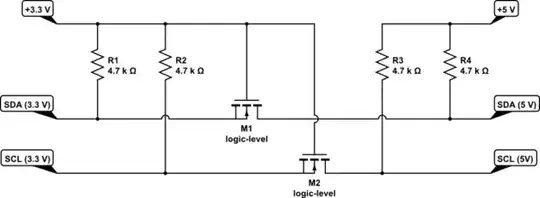
simulate this circuit – Schematic created using CircuitLab
evildemonic
- 9,209
- 2
- 26
- 46
-
@Justme "Are you sure the FETs are the right way around?" I believe I have them correct. "The FET Source pin should be on the higher voltage side, or the intrinsic diode will push higher voltage towards the lower voltage bus." This is backwards. With N-MOS you want the source to be the lower potential, otherwise the body diode (not shown here) will conduct. Think about a typical N-MOS situation, you usually have the source grounded and the drain at positive potential. – evildemonic Aug 13 '20 at 17:42
-
0
I would power the HCT parts at 5V. Their outputs would be 5V for HIGH which, I believe, can still be read by the MCP23017 safely even if only driven at 3.3V
The maximum input voltage for a MCP23017 on a 3.3 volt supply is 3.9 volts - read page 3 of data sheet: -

If this is limited to less than 20 mA then maybe you'll be OK. I haven't looked into what the generic HCT output current is.
Andy aka
- 456,226
- 28
- 367
- 807
-
Gotcha so per the datasheet, the MCP23017 will not like a 5v input if powered at 3.3V. I woulld use a bi-directional level shifter in the design for the i2c pins but I am constructing a kit with all through-hole components I cannot find a bi-directional level shifter in a dip package. Also, I have seen designs using the BSS138 but it appears to only be available in surface mount. – Kevin McQuown Aug 13 '20 at 14:41
-
@KevinMcQuown The BSS138 is an N-channel enhancement-mode MOSFET, not a specific integrated circit. There are a few MOSFETs that are similar, yet packaged in a through-hole package (this post discusses some as well as the important parameters to select a MOSFET for this application; they will usually be TO-92 transistor packages rather than DIP). – nanofarad Aug 13 '20 at 14:57
-
Interesting, so the TN0702 might be a replacement for the BSS138 that could then be soldered by students and give me proper level shifting for I2C. I don't need to run the i2c bus faster than 100kHz – Kevin McQuown Aug 13 '20 at 15:04
-
How many lines are there to level shift compared to how many lines between MCU and MCP23017 @KevinMcQuown – Andy aka Aug 13 '20 at 17:39
-
I only need to level shift the I2C lines, SDA & SCL going from MCU to MCP23017 – Kevin McQuown Aug 15 '20 at 17:06
-
-