1

I have found this circuit which is supposed to be a current-limiting circuit:

schematic

simulate this circuit – Schematic created using CircuitLab

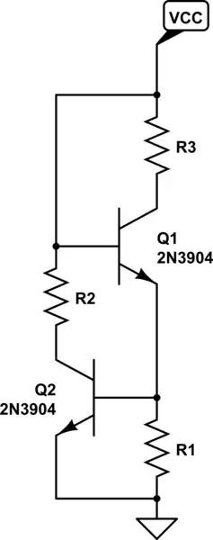
'R1 is used as a current's resistor. It monitors the current flowing through Q1. The voltage drop across R1 increases as the current through Q1 increases. If the voltage at the top of R1 reaches 0.65V Q2 begins to turn on. Q2 diverts some of the current from the base of Q1 and sends it to ground. This reduces Q1's collector current'.

However, I am having trouble understanding this:

When Q2 is on the voltage drop of R1 will become less and Q2 must be off despite we say it is on and this will create a closed loop of paradoxes.

Where am I wrong?

JRE
  • 71,321
  • 10
  • 107
  • 188
Helena Wells
  • 304
  • 2
  • 11

2 Answers2

4

You have transcribed the circuit from physics.unlv.edu incorrectly.

schematic

simulate this circuit – Schematic created using CircuitLab

Figure 1. (a) What you have drawn. (b) The corrected version. (c) The original circuit.

Your R2 should be providing the bias for Q1 and Q2's collector should be connected directly to the base of Q1. This way when the voltage across R1 reaches 0.65 V or so Q2 will start to steal the bias from Q1.

In its modified form of Figure 1c the enable signal provides the bias. The 5 V supply is adequate because Q6's emitter will be at 0.65 V and its base at about 0.65 V above that - so 1.3 V above ground.


From the comments:

OP wants to know about the edge case transition at about 0.65 V and why it is continuous and stable, which this answer does not really address.

schematic

simulate this circuit

Figure 2. The equivalent circuit.

I don't think there's much point in discussing the stability of this circuit. It's a pair of PN junctions shorting out VCC to ground. It won't last long.

Transistor
  • 175,532
  • 13
  • 190
  • 404
  • Good error spot +1 – Andy aka Jul 20 '20 at 08:16
  • Though you noticed an important correction, this doesn't seem to answer the question at hand. OP wants to know about the edge case transition at about 0.65 V and why it is continuous and stable, which this answer does not really address. – Groger Jul 20 '20 at 12:46
  • @Groger: The OP's circuit is a pair of series-connected PN junctions shorting out the power supply. It won't be stable as there will be continuous temperature rise until Q1 or Q2 burns out. Do you see some other solution? – Transistor Jul 20 '20 at 13:00
  • I agree that there is a problem in OP's circuit, which you addressed well. This should be handled as a question comment or edit, perhaps. This answer does not address the actual question from OP, "When Q2 is on the voltage drop of R1 will become less and Q2 must be off despite we say it is on and this will create a closed loop of paradoxes.

    Where am I wrong?".

    – Groger Jul 20 '20 at 13:09
  • See the update. – Transistor Jul 20 '20 at 13:13
0

The difficulty you have in resolving this paradox stems from the treatment of transistors as binary, digital elements. In reality, transistors are analog, and have gradual, continuous behavior. In the case of switches, like the realm of digital, this middle region is ignored, and only saturation and cutoff behaviors are considered, in which case we have our typical amplifiers.

A more general treatment of transistors would be with this equation

\$i_C=I_Se^{\frac{v_{BE}}{V_T}}(1+\frac{V_{CE}}{V_A})\$

In this case, a transistor can always be considered to have a collector current flowing (except with all grounded pins), rather than a drastic transition. For general purposes, the electrical engineering community accepts \$0.65 V\$ or \$0.7 V\$ as the "turn on" voltage, but in reality, current flows long before that.

In the case of your circuit, \$Q_2\$ will always be taking a little bit of current from \$R_1\$, but for voltages less than the turn on voltage, this is miniscule enough that it can be ignored. As the voltage across \$R_1\$ increases,this current diverting effect becomes more dramatic, limiting the current through \$R_1\$.

Groger
  • 118
  • 6