3

In this post, the gentleman describes this device but does not give any details about how it works. What's underneath the shrink tube?

The easiest way to explain my Low Drop Constant Current Driver (LDCCD) is as follows. It converts the voltage and current of the LiPo to a constant current and voltage suitable for the LED's included in the light set so the LED's remain a consistent brightness as the LiPo discharges. My LDCCD doesn't use resistors to reduce the voltage and current, resistors will shorten flight time as they use additional power to regulate the voltage and current.

For the Ladybird 8-LED Light Set the LDCCD I've built for this application takes the 240mAh and 4.2 V of the LiPo down to a constant 3.0V @ 30mAh for Blue, Green, White LED's and 2.7V @ 30mAh for Red LED's. This particular LDCCD will work with 2S @ 7.2V and 3S @ 11.1V as well. enter image description here

Mark Harrison
  • 10,651
  • 27
  • 70
  • 99
  • 3
    The answers so far are suggesting that it's a linear, FET-based current regulator. However, while such a circuit would have tighter control over the current, it would not save any energy relative to using a resistor delivering the same amount of current, as claimed by the inventor. The only way to do that would be to use a switching current regulator. – Dave Tweed Dec 10 '12 at 01:22

3 Answers3

6

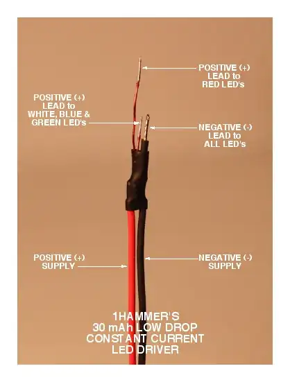
While the inventor has made certain claims in their post, the vagueness and errors in terminology used indicate a possibility that the claims are not necessarily all tried and tested.

Specifically: The phrase "takes the 240mAh and 4.2 V of the LiPo down to a constant 3.0V @ 30mAh for ..." is clearly more sales-speak than veracity.

  • One doesn't regulate capacity (mAh) down to anything, just current (mA).
  • For a constant current driver other than a switching driver, the output voltage will not be fixed to 3.0V or whatever, it would regulate itself precisely to the forward voltage of the LED connected to it.

It thus appears that the description is of a switching current regulator, such as the Supertex HV9923 3-Pin Switch-Mode LED Lamp Driver IC. This is not necessarily the specific part used, but it would work for the purpose, with a few additional components. The size of the circuit can be made smaller than the heat shrink covered package in the question.

To take this even further, the Fairchild FAN5616 High-Efficiency Constant-Current LED Driver can actually use input voltages lower than the LED's forward voltage, and provide 3 channels of regulated drive current (up to 40 mA each), at efficiency of up to 90%. The device has an internal charge pump that raises the voltage by 1x to 2x. No personal experience on this part, though.

If one takes the inventor's claims with a bit of skepticism, a suitable alternative component is the SuperTex CL330 3-Channel 30mA Linear LED Driver, which can be used to sink a constant 30 mA per channel using just one additional component, a 100 nF capacitor. Resultant size would be minuscule.

If one limits the current to 25 mA instead of 30, an even smaller and simpler, single component 2 terminal device alternative is the SuperTex CL25, a tiny TO-243AA (SOT-89) 1.6 x 4.25 x 2.6 mm component. The efficiency of switching is lost, but the advantage is a single component in the current path, hence either source or sink, and no support components needed. There may be 30 mA equivalents available, I am not aware of them.


For all the Supertex parts mentioned, they are very generous in their sampling: They sent out a pack of 10 to 20 pieces each, for the components mentioned above as well as the CL220 and a few others, against a request for just 5 pieces of the CL25 for an evaluation.

I don't have personal experience with the Fairchild device and cannot vouch for it. They do not send out samples to my geography for some reason, they do not sell many of their LED regulation parts here, and local distributors do not carry the part.

Anindo Ghosh
  • 50,446
  • 8
  • 105
  • 201
  • I'm not an expert in reading datasheets, but many of these parts specify higher minimum input voltages than a single cell Lipo can supply. Unfortunate, as I'm looking for a similar solution myself – Greg Woods Nov 25 '14 at 15:46
2

The blob probably contains an opamp, a MOSFET, a sense resistor and some form of voltage reference. The Voltage reference could be 2 resistors dividing the Vsupply and still give enough accuracy across typical LiFePO4 Vout values.

The name is wrong and rating is wrong. But the device sounds sound and useful. It is a 'low DROPOUT constant current driver rated at 30 mA (not 30 mAH). ie the current source works with very little drop across the circuit when necessary to do so. Typically this can be 0.1V or so for a sense resistor voltage drop plus a minimal amount for a series control element such as a low Rdson MOSFET.


It is almost certainly "just" a small sense resistor in series with a pass transistor (usually a MOSFET) that is controlled so as to maintain a constant voltage across the sense resistor. eg if the sense voltage is 0.1 Volt and the current is 30 mA then Rsense = Vsense/Isense = 0.1/0.030 ~= 3.3 Ohms. An opamp (usually) monitors Vsense and keeps it at 0.1V. Lower sense voltages than 0.1V are possible but if you get too low the typical offset voltage error of the opamp starts to become large relative to the sense voltage and this causes the current to vary depending on opamp offset voltage.

LiFePO4 usable Vout depends on loading but for loads of say C/10 max then 3.1V would be a useful end of battery life and you can then regulate down to V_battery_minimum - Vsense = 3.1 - 0.1 = 3.0V.

Russell McMahon
  • 150,303
  • 18
  • 213
  • 391
2

Multiple vendors make constant current LED drives. The most simple of these have a constant current sink which can be programmed by setting a resistor value. They are low drop since most are FET based and need little head room to maintain current control. For example see MAX1916 (from Maxim) or CAT4003 (OnSemi). One would need little more than one of these devices, and a set resistor soldered up to make the circuit.

Nick Alexeev
  • 38,181
  • 17
  • 100
  • 237
gsills
  • 7,213
  • 17
  • 22
  • By being MOSFET based, how does a current driver thereby become low drop? – Seemingly So Dec 10 '12 at 15:03
  • A FET based current sink is low drop because the FET can control the current while having a very low Vds. Compared to a BJT, which would lose control (saturated) with a Vce around 0.6V, the FET is low drop. Even a FET with Rdson of 22 Ohms would out perform a BJT at these current levels. – gsills Dec 10 '12 at 17:33