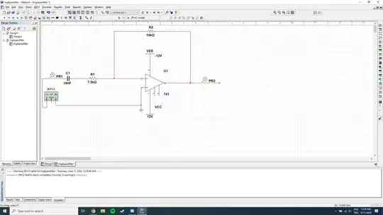
I have this high-pass filter schematic and its AC Sweep simulation. Until the break through the end, the graph is right, but I can't see why the graph breaks on the right hand side and the filter behaves like a band-pass circuit.

I have this high-pass filter schematic and its AC Sweep simulation. Until the break through the end, the graph is right, but I can't see why the graph breaks on the right hand side and the filter behaves like a band-pass circuit.
You’re high pass filter with corner frequency of 1.178khz works well for frequencies under 100khz however as you approach 500khz your gain will drop due to the inherent bandwidth given by the op amp. For a gain of 2V/V and gain bandwidth of 1MHz(for a 741 op amp), you have about 500khz of bandwidth, hence why your voltage gain appears like low pass towards 500khz region and higher. If you choose an op amp with higher gain bandwidth, ie: 10 or 20 MHz or even op amps with 100MHz your circuit will be more like a highpass for higher frequencies. Note that: even with op amps with 250MHz gain bandwidth, you will eventually decrease gain at some point in the upper frequency limit as all op amps have finite bandwidth.