0

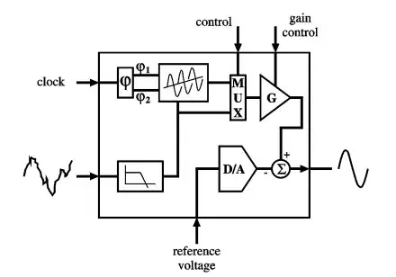
If one has a chip in mind where the chip has analog and digital functions and sub systems, before designing the chip there is always a functional block diagram as the following one:

enter image description here

I'm wondering how are they drawn? I used some SPICE simulators and board level design tools as hobbyist. But didn't encounter a tool which involves specific shapes for drawing such functional diagrams for electronics as in the above example. Is there standard for such symbols or people draw these things by hand?
user1245
  • 4,125
  • 4
  • 38
  • 95
  • 2
    I’m voting to close this question because this is not particularly about EE and is more generally about how to draw things with pretty shapes and possibly different colours and shades. – Andy aka May 26 '20 at 10:56
  • 4
    These are drawn by a draftswoman or -man using a vector illustration software, like Corel Draw, Adobe Illustrator, or typeset using e.g. LaTeX and TikZ. (may I note that for a couple of reasons, this is not a good diagram, and it does not please me aesthetically, either.)

    The hobbyist-level and free tool to do so would probably be inkscape.

    – Marcus Müller May 26 '20 at 10:56
  • You can use Simulink. But the diagrams you see in the datasheet are mainly made using Adobe Illustrator. – Sadat Rafi May 26 '20 at 11:30
  • The comments above would be right unless (one of) your purpose(s) is to have a functionality of those blocks. As in, place them, simulate, analyze, etc. Reading your question doesn't show any sign of these. If they exist, can you modify your question to be more clear about your goal with these blocks? – a concerned citizen May 26 '20 at 19:43

1 Answers1

0

Is there a standard for such symbols or people draw these things by hand?

For a lot of things in flow charts, there are standards; it depends from the context, for most:

For example, there's a rich canon of standards symbols from signal processing and control theory, for example for low-pass filters, for error detectors, oscillators, etc.

Data processing has its own types of diagrams - with symbols for memory, processes, data transformations...

Same applies to chemical processing, motor control, climate control...

So, yes, there's standards, but they typically arise from the application field the user of an IC might be versed in.

Marcus Müller
  • 94,373
  • 5
  • 139
  • 252