0

schematic

simulate this circuit – Schematic created using CircuitLab

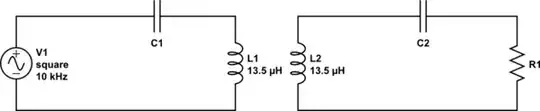
I've run in to some trouble, working out wether i need to use a RLC or just a LC tank for my circuit. My circuit is an H-bridge, where i need to use either LC or RLC on the output, to make a sine wave. Do you guys or gals and any tips or tricks, or just simple explaining to me, why one is better than the other. //Thanks!

gamerEgirl
  • 15
  • 6
  • 3
    With every L comes an R so, your question is RLC or RLC? basically. – Andy aka May 19 '20 at 13:51
  • 1
    If it's from an ideal POV, the R is just dissipative, OTOH you'll need some load, but that comes across the cap, but then both L and C may have their series or parallel resistance... I think what I'm trying to say is that you gave precious little information. What tank? What H-bridge? I suppose switching regime, then what frequency for the carrier and the signal? What is "better"? etc – a concerned citizen May 19 '20 at 14:06
  • Thanks for the answer! I've updated my question and added a schematic, where V1 is the signal coming from the H-bridge. R1 is a load, and the place i need to transfer all the power. I have no idea though, wether i should use a resistor on the left side, or just keep it with just a LC. – gamerEgirl May 20 '20 at 06:52

0 Answers0