I'm implementing a 300V MOSFET H Bridge with IR2110 driver.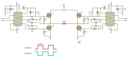 I decided to first try it in low (and safe) voltages, thus replacing the 300V with 12V as shown in the diagram. The MOSFETs I'm using are P20NM60FP, with a VGS of 5V.
Ideally, I should have this waveform at output load
I decided to first try it in low (and safe) voltages, thus replacing the 300V with 12V as shown in the diagram. The MOSFETs I'm using are P20NM60FP, with a VGS of 5V.
Ideally, I should have this waveform at output load 
I've checked every connection and the control signal from my microcontroller is correct (5V high, 1 Hz frequency). However, when I tried it, I get this spiky waveform as a result. Any ideas as to why is this happening?


