1

I think some logic IC input can handle a range of lower voltage levels but will output at supply voltage...

What is the best way to achieve an input that can handle higher levels but output at a lower level for the next stage? Some logic ICs or circuits that can do this?

not dealing with high speeds, 5kHz max.

5v logic with 5-10V input range

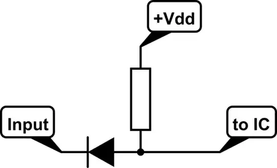
What about a zener on the input?

Jay
  • 309
  • 1
  • 8
  • 1
    What voltages specifically do you need? Logic that can be powered by 3.3 (or maybe 2.5 or even 1.8 V) with 5-V-tolerant inputs is fairly common. – The Photon Apr 13 '20 at 22:31
  • @ThePhoton 5V output and up to 10V tolerant input – Jay Apr 13 '20 at 22:37
  • 3
    Specify the maximum voltage to be treated as a LOW, the minimum voltage to be treated as a HIGH, and specify similarly for the output along with how many loads must support at those specs. What is the input impedance to be, also? – jonk Apr 13 '20 at 22:38
  • Also does it need to have hysteresis – Spehro Pefhany Apr 13 '20 at 22:44
  • The simplest IC of this kind is called resistor divider. – Marko Buršič Apr 13 '20 at 22:48
  • @jonk typical 5V levels that handle or ''clip'' input voltages up to 10V, from what i seen in datasheets it's low<1.5v high>3.5V.

    typical load would probably be driving 1 or 2 CMOS inputs, input impedance is not critial

    – Jay Apr 13 '20 at 23:23
  • voltage divider wont work, it needs work with 5V to 10V, dropping 10V input to 5V through a divider will leave a 5V input at 2.5V, too low to trigger input. – Jay Apr 13 '20 at 23:32
  • An opto-isolator on the input side can do this, are you wanting to use the same pin for both input and outputs? – Ron Beyer Apr 13 '20 at 23:35
  • @Jay, please edit your question to include these requirements (output voltage, range of input voltage, input impedance, ...) – The Photon Apr 13 '20 at 23:48
  • @Jay what supply rails do you have handy? And are you saying that you merely want 10 V tolerant inputs, but that you want the input specifications of a typical 5 V input? – jonk Apr 14 '20 at 05:57
  • @jonk there is only 5V rail for the digital circuits, plus the logic ICs Ill be using are all rated at 5.5V max.

    And yes that sums it up.

    – Jay Apr 14 '20 at 06:23

2 Answers2

2

How to make a low-speed digital input tolerant against voltages > Vdd:

schematic

simulate this circuit – Schematic created using CircuitLab

Ignore anything but 0V on the input. That's what the diode does. Pullup to +Vdd if not 0V. If the IC has a built-in pullup (e.g. TTL behaves this way, and also many µC) you can leave out the external one.

Janka
  • 14,276
  • 1
  • 21
  • 35
  • Wouldnt the high threshold be practically nonexistent? For a static voltage a zener diode seems like it could achieve this without affecting threshold of the input, not sure how it would behave with a switching input. – Jay Apr 14 '20 at 02:08
  • For TTL, input levels between 0.8V and 2.7V are forbidden. So there isn't a high threshold it could affect, only that "forbidden zone". For CMOS, input voltages below 20V will be shorted by the high-side protection diode on the input, and those above will punch though the gate oxide and fry the chip. A Zener has too much capacitance to be any help. (This is for logic ICs, for higher integrated CMOS parts the limit is usually 8…10V.) – Janka Apr 15 '20 at 04:11
  • too much capacitance for 5kHz? seems to be in ballpark of 100pf, with 10k current limiter thats 150kHz cutoff. Everyone seems reluctant to even suggest the potential problems that may arise from this in general logic applications without having the exact details of my particular application but after some reading I think maybe the concerns here are delay and dull edges? neither should matter here. – Jay Apr 15 '20 at 23:42
  • It's not the 5kHz that matters but the rise time. That one may be in the µs range. But as stated before, your zener is useless anyway as there is a protection diode inside the chip that shorts to +Vdd much faster than the Zener could react. As long the input voltage is below roughly 20V for CMOS logic chips or 8..10V for CMOS µCs. And above, the gate oxide is toast before the zener reacts. – Janka Apr 16 '20 at 09:48
0

There are several options that could work

  • Use a voltage divider, and receive the signal using TTL-compatible inputs (i.e. HCT family parts) to allow for low \$V_{IH}\$ levels when the incoming signal is at 5 V levels.

  • Use an open-drain output on the high-voltage side, with pull-ups to the receiver's Vdd.

  • Use a diode connection as shown in the answer by Janka.

  • Use a zener-diode limiter to ensure the receiver's input isn't driven above, say, 4.5 V, even when the sender is driving 10 V.

  • ...

The best choice depends on unstated requirements like

  • data rate

  • propagation delay requirements

  • need to allow for even higher over-voltages (could the 10 V occasionally be 15 or 25 V momentarily?)

  • power consumption requirements

  • cost

  • ...

The Photon
  • 129,671
  • 3
  • 164
  • 309
  • Is there any reason no one other than you has suggested or agreed with the idea of using a zener, as it seems to be ideal? – Jay Apr 14 '20 at 23:41
  • @Jay There are even more options than I've seen listed here. Some of those in my head, not present here, I might even prefer over any of these so far. But there just isn't enough context for me to know what to offer. You are in a much better position. If you like a zener, then a zener it is. – jonk Apr 15 '20 at 04:48